Microwave Networks
CM 100Base-T System User’s Manual
11/18/03
Page 3-12-5
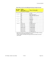
Table 3-12-B. SCU S1 and S2 DIP-Switch Settings for Digital Channels
DIP-Switch
Position
Setting
Switch logic:
ON=closed; OFF=open
Channel Configuration
Factory defaults in bold: Not used, Normal, 2 stop bits, 1 parity bit, 8 data bits, 9.6 kbps
1
OFF
Not used
2
ON
Bypass data channel *
*
Bypass mode lets the SCU automatically adjust to the pattern and format of incoming
data, but is not recommended for use above 2.4 kbps.
In Normal operation SCU DIP-switch settings must match the pattern and format of
incoming data.
OFF
Normal data channel operation
3
ON
1 stop bit
OFF
2 stop bits
4
ON
No parity bit
OFF
1 parity bit
5
ON
7 bit data
OFF
8 bit data
6, 7, 8
ON, ON, ON
19.2 kbps data rate
ON, ON, OFF
9.6 kbps data rate
ON, OFF, ON
4.8 kbps data rate
ON, OFF, OFF
2.4 kbps data rate
OFF, ON, ON
1.2 kbps data rate
OFF, ON, OFF
0.6 kbps data rate
OFF, OFF, ON
0.3 kbps data rate
OFF, OFF, OFF
0.15 kbps data rate
Summary of Contents for CM7
Page 2: ......
Page 4: ...Page iv 5 04 05 CM7 8 100Base T System User s Manual ...
Page 16: ...Glossary Page xvi CM System Users Manual X Y Z ...
Page 24: ...Microwave Networks CM7 8 100Base T System User s Manual Pagexxiv ...
Page 62: ...Chapter 2 Operation Page 2 18 5 02 05 CM 100Base T System User s Manual ...
Page 64: ...Chapter 3 Module Descriptions Page 3 2 CM7 8 100Base T ...
Page 88: ...Section 3 3 Transmitter Unit Page 3 3 6 CM7 8 System User s Manual ...
Page 96: ...Section 3 5 RF Power Supply Unit Page 3 5 4 CM System User s Manual ...
Page 100: ...Section 3 6 SP Power Supply Unit Page 3 6 4 CM System User s Manual ...
Page 106: ...Section 3 7 Alarm and Control Unit Page 3 7 6 11 18 03 CM 100Base T System User s Manual ...
Page 124: ...Section 3 11 SYNDES Page 3 11 6 CM System User s Manual ...
Page 130: ...Section 3 12 SCU Page 3 12 6 11 18 03 CM 100Base T System User s Manual ...
Page 138: ...Section 3 13 OWU Page 3 13 8 CM System User s Manual ...
Page 150: ...Section 3 15 NMU Page 3 15 6 CM System User s Manual ...
Page 192: ...Chapter 5 Verification Page 5 20 CM System User s Manual ...
Page 194: ...Chapter 6 Maintenance Page 6 2 7 23 03 CM 100Base T System User s Manual ...
Page 224: ...Chapter 6 Maintenance Page 6 32 7 23 03 CM 100Base T System User s Manual ...
Page 226: ...Site Engineering Page 2 CM System User s Manual ...
Page 230: ...Appendix A T I Curves Page A 4 CM7 8 100Base T System User s Manual ...
Page 267: ...Microwave Networks CM System User s Manual PageB 37 ...
Page 268: ...Appendix B QuikLink Page B 38 CM System User s Manual ...
Page 282: ...Appendix D Alarm Codes Page D 6 5 02 05 CM 100Base T System User s Manual ...
Page 290: ...Appendix E Setting Frequency Page E 8 CM7 8 System User s Manual ...
Page 312: ...CM7 8 100Base T System User s Manual Page I 4 Microwave Networks ...

