Microwave Networks
CM System User’s Manual
Page 3-13-7
Configuring the Orderwire, Service Channel, and Bridge
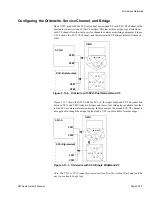
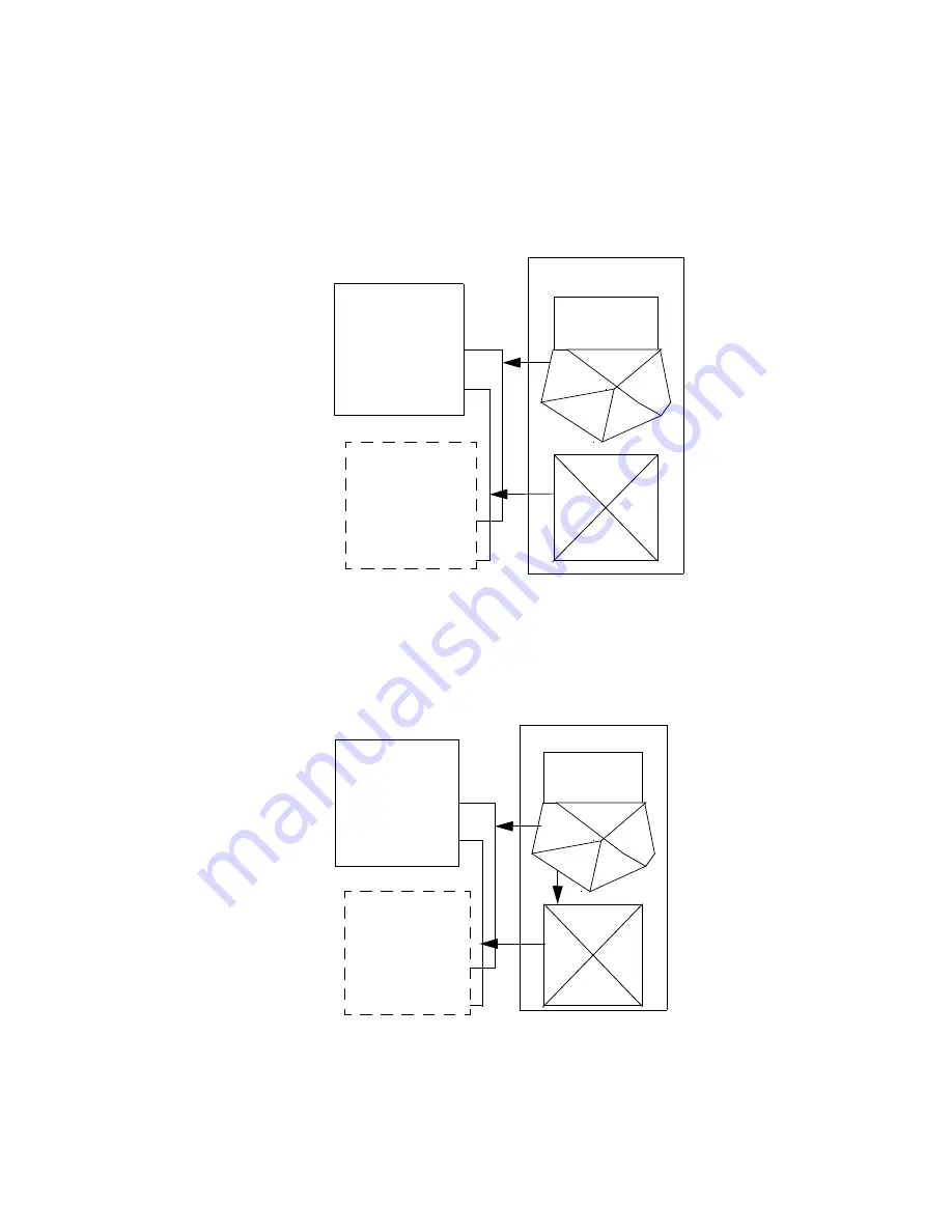
On an OWU used with the SCU set for dual narrowband VF each SCU VF channel of the
host radio connects to one of two VF bridges. This leaves three bridge legs available on
each VF channel for other radio service channels or alarm monitoring equipment. Figure
3-13-6 shows two SCU VF channels and their associated VF bridges isolated from each
other.
Figure 3-13-7 shows the OWU with the SCU set for single wideband VF. The connection
between VF13 and VF23 links two bridges and leaves four bridge legs available for other
radio SCUs or external alarm monitoring. In this example, the second SCU VF channel is
not applicable, though the bridge leg labeled SCU #2 is not available for other usage.
Note: The VF13 to VF23 connection is made externally at the terminal block and could be
any two available bridge legs.
Figure 3-13-6. Orderwire with SCU-Dual Narrow Band VF
OWU
SCU-A
VF#1
VF#2
SCU-B (protected)
VF#1
VF#2
Internal
VF
1
1
VF
12
V
F1
3
S
C
U
1
VF 23
VF 22
VF 21
SCU 2
Figure 3-13-7. Orderwire with SCU-Single WideBand VF
OWU
SCU-A
VF#1
VF#2
SCU-B (protected)
VF#1
VF#2
Internal
V
F
1
1
VF
12
V
F1
3
S
C
U
1
VF 23
VF 22
VF 21
SCU 2
Summary of Contents for CM7
Page 2: ......
Page 4: ...Page iv 5 04 05 CM7 8 100Base T System User s Manual ...
Page 16: ...Glossary Page xvi CM System Users Manual X Y Z ...
Page 24: ...Microwave Networks CM7 8 100Base T System User s Manual Pagexxiv ...
Page 62: ...Chapter 2 Operation Page 2 18 5 02 05 CM 100Base T System User s Manual ...
Page 64: ...Chapter 3 Module Descriptions Page 3 2 CM7 8 100Base T ...
Page 88: ...Section 3 3 Transmitter Unit Page 3 3 6 CM7 8 System User s Manual ...
Page 96: ...Section 3 5 RF Power Supply Unit Page 3 5 4 CM System User s Manual ...
Page 100: ...Section 3 6 SP Power Supply Unit Page 3 6 4 CM System User s Manual ...
Page 106: ...Section 3 7 Alarm and Control Unit Page 3 7 6 11 18 03 CM 100Base T System User s Manual ...
Page 124: ...Section 3 11 SYNDES Page 3 11 6 CM System User s Manual ...
Page 130: ...Section 3 12 SCU Page 3 12 6 11 18 03 CM 100Base T System User s Manual ...
Page 138: ...Section 3 13 OWU Page 3 13 8 CM System User s Manual ...
Page 150: ...Section 3 15 NMU Page 3 15 6 CM System User s Manual ...
Page 192: ...Chapter 5 Verification Page 5 20 CM System User s Manual ...
Page 194: ...Chapter 6 Maintenance Page 6 2 7 23 03 CM 100Base T System User s Manual ...
Page 224: ...Chapter 6 Maintenance Page 6 32 7 23 03 CM 100Base T System User s Manual ...
Page 226: ...Site Engineering Page 2 CM System User s Manual ...
Page 230: ...Appendix A T I Curves Page A 4 CM7 8 100Base T System User s Manual ...
Page 267: ...Microwave Networks CM System User s Manual PageB 37 ...
Page 268: ...Appendix B QuikLink Page B 38 CM System User s Manual ...
Page 282: ...Appendix D Alarm Codes Page D 6 5 02 05 CM 100Base T System User s Manual ...
Page 290: ...Appendix E Setting Frequency Page E 8 CM7 8 System User s Manual ...
Page 312: ...CM7 8 100Base T System User s Manual Page I 4 Microwave Networks ...

