Section 3-14
WTU
Page 3-14-2
2/20/04
CM System User’s Manual
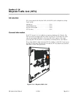
Functional Description
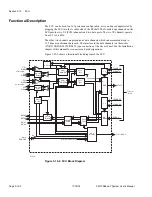
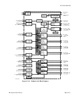
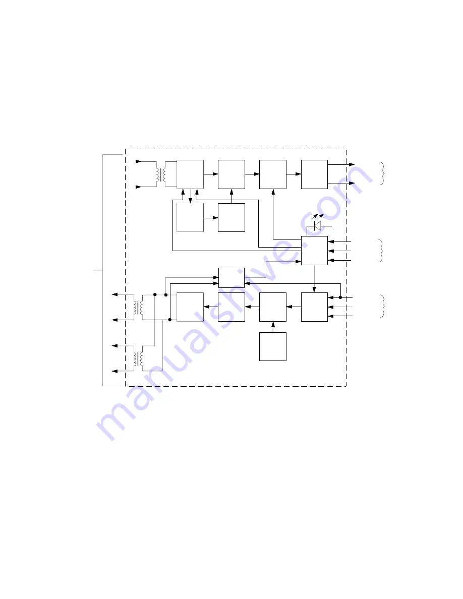
Figure 3-14-2 shows signals through the WTU. On the transmit side, the WTU accepts
one DS1/E1 signal and one asynchronous data signal (up to 9600 bps) from the access
panel. The module recovers the clock from the DS1/ E1 signal, and converts the signal
and the asynchronous data signal into an NRZ TTL format. The clock and NRZ data for
both channels are sent to the MUX.
On the receive side, the WTU accepts one clock and two NRZ data signals from the
MUX. The module converts the clock signal and the first NRZ data signal into a DS1 or
E1 format, and the second NRZ data signal into an RS-423 format. These signals are sent
to the access panel for customer access.
The modules include a 1x1 protection switch required for system maintenance. Note that
wayside traffic is switched independent of the primary DS1/E1 or DS3 traffic.
DS1/E1
Input
F-0133-A
Line
Interface
Transmit
De-Jitter
AMI/B8ZS
Decoder
3-State
Drivers
XFMR
NRZ Data
NRZ CLK
To MUX
Clk
Recovery
PLL
Line
Interface
Receive
Line
Coder
FIFO
3-State
Buffers
NRZ Data
NRZ CLK
FR CLK
From
MUX
Code
Select
Module
Fail
ACU Data
ACU ADDR
ACU R/W
To/From
ACU
47.879
MHz
OSC
Thru/
Cross Sel
Los
AIS Control
LB Select
XFMR
XFMR
DS1/E1
Output
Monitor
Alarm
and
Control
Interface
Activity
Detector
To
Terminal
Block
Figure 3-14-2. Signal Flow Through the Wayside Traffic Unit
Summary of Contents for CM7
Page 2: ......
Page 4: ...Page iv 5 04 05 CM7 8 100Base T System User s Manual ...
Page 16: ...Glossary Page xvi CM System Users Manual X Y Z ...
Page 24: ...Microwave Networks CM7 8 100Base T System User s Manual Pagexxiv ...
Page 62: ...Chapter 2 Operation Page 2 18 5 02 05 CM 100Base T System User s Manual ...
Page 64: ...Chapter 3 Module Descriptions Page 3 2 CM7 8 100Base T ...
Page 88: ...Section 3 3 Transmitter Unit Page 3 3 6 CM7 8 System User s Manual ...
Page 96: ...Section 3 5 RF Power Supply Unit Page 3 5 4 CM System User s Manual ...
Page 100: ...Section 3 6 SP Power Supply Unit Page 3 6 4 CM System User s Manual ...
Page 106: ...Section 3 7 Alarm and Control Unit Page 3 7 6 11 18 03 CM 100Base T System User s Manual ...
Page 124: ...Section 3 11 SYNDES Page 3 11 6 CM System User s Manual ...
Page 130: ...Section 3 12 SCU Page 3 12 6 11 18 03 CM 100Base T System User s Manual ...
Page 138: ...Section 3 13 OWU Page 3 13 8 CM System User s Manual ...
Page 150: ...Section 3 15 NMU Page 3 15 6 CM System User s Manual ...
Page 192: ...Chapter 5 Verification Page 5 20 CM System User s Manual ...
Page 194: ...Chapter 6 Maintenance Page 6 2 7 23 03 CM 100Base T System User s Manual ...
Page 224: ...Chapter 6 Maintenance Page 6 32 7 23 03 CM 100Base T System User s Manual ...
Page 226: ...Site Engineering Page 2 CM System User s Manual ...
Page 230: ...Appendix A T I Curves Page A 4 CM7 8 100Base T System User s Manual ...
Page 267: ...Microwave Networks CM System User s Manual PageB 37 ...
Page 268: ...Appendix B QuikLink Page B 38 CM System User s Manual ...
Page 282: ...Appendix D Alarm Codes Page D 6 5 02 05 CM 100Base T System User s Manual ...
Page 290: ...Appendix E Setting Frequency Page E 8 CM7 8 System User s Manual ...
Page 312: ...CM7 8 100Base T System User s Manual Page I 4 Microwave Networks ...

