Section 3-14
WTU
Page 3-14-4
2/20/04
CM System User’s Manual
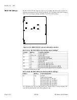
MLN7330 Settings
The MLN7330 WTU that supports
North American
digital signal hierarchy contains five
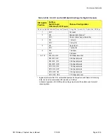
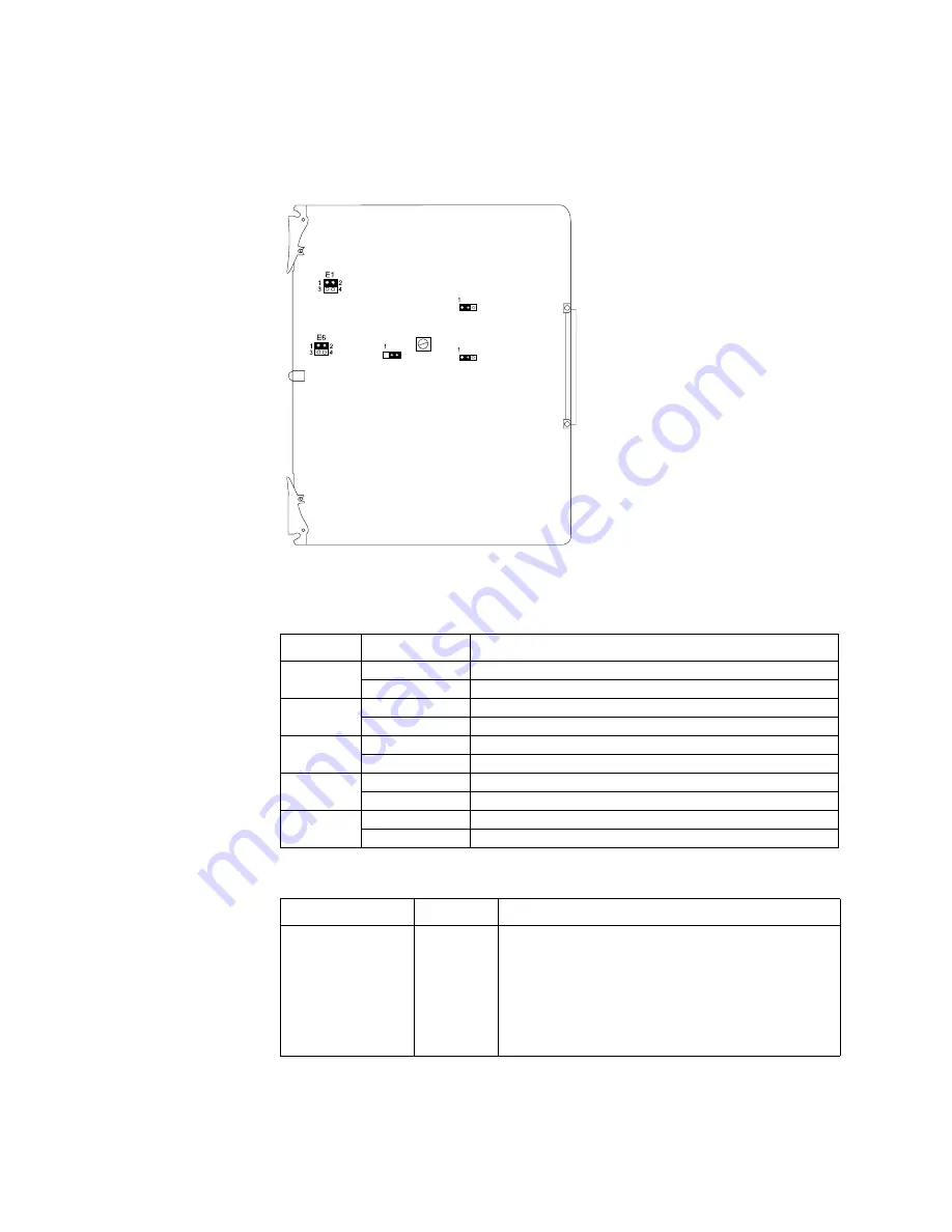
configuration jumpers and one switch. See Figure 3-14-4 for jumper and switch locations,
Table 3-14-A for jumper settings, and Table 3-14-B for switch settings.
Use a flat-head screw driver to change the rotary switch setting by turning the rotary dial
even with the marking line for the line buildout setting.
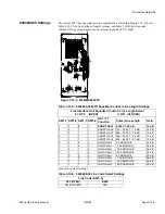
Table 3-14-A. MLN7330 WTU Line Coding Jumper Settings*
Jumper
Setting
Function Enabled
E1
1-2
Normal operation
1-3, 2-4, 3-4
Factory test
E3
1-2
DS1 channel equipped
2-3
DS1 channel not equipped
E6
1-2
Normal operation
1-3, 3-4
Factory test
E8
1-2
DS1 channel - AMI line code
2-3
DS1 channel - B8ZS line code
E10
1-2
Asynchronous data channel receiver enabled
2-3
Asynchronous data channel receiver disabled
* Jumpers not listed are not used
Table 3-14-B. MLN7330 WTU Line Buildout Switch Settings
Switch
Setting
Function Enabled
K2
0—8
not used
1
Channel Not Equipped
9
DS1 line buildout 1 to 131 feet
A
DS1 line buildout 131 to 262 feet
B
DS1 line buildout 262 to 393 feet
C
DS1 line buildout 393 to 524 feet
D
DS1 line buildout 524 to 655 feet
F - 0 1 1 1
E 8
K 2
E 3
E 1 0
Figure 3-14-4. MLN7330 WTU Jumper and Switch Locations
Summary of Contents for CM7
Page 2: ......
Page 4: ...Page iv 5 04 05 CM7 8 100Base T System User s Manual ...
Page 16: ...Glossary Page xvi CM System Users Manual X Y Z ...
Page 24: ...Microwave Networks CM7 8 100Base T System User s Manual Pagexxiv ...
Page 62: ...Chapter 2 Operation Page 2 18 5 02 05 CM 100Base T System User s Manual ...
Page 64: ...Chapter 3 Module Descriptions Page 3 2 CM7 8 100Base T ...
Page 88: ...Section 3 3 Transmitter Unit Page 3 3 6 CM7 8 System User s Manual ...
Page 96: ...Section 3 5 RF Power Supply Unit Page 3 5 4 CM System User s Manual ...
Page 100: ...Section 3 6 SP Power Supply Unit Page 3 6 4 CM System User s Manual ...
Page 106: ...Section 3 7 Alarm and Control Unit Page 3 7 6 11 18 03 CM 100Base T System User s Manual ...
Page 124: ...Section 3 11 SYNDES Page 3 11 6 CM System User s Manual ...
Page 130: ...Section 3 12 SCU Page 3 12 6 11 18 03 CM 100Base T System User s Manual ...
Page 138: ...Section 3 13 OWU Page 3 13 8 CM System User s Manual ...
Page 150: ...Section 3 15 NMU Page 3 15 6 CM System User s Manual ...
Page 192: ...Chapter 5 Verification Page 5 20 CM System User s Manual ...
Page 194: ...Chapter 6 Maintenance Page 6 2 7 23 03 CM 100Base T System User s Manual ...
Page 224: ...Chapter 6 Maintenance Page 6 32 7 23 03 CM 100Base T System User s Manual ...
Page 226: ...Site Engineering Page 2 CM System User s Manual ...
Page 230: ...Appendix A T I Curves Page A 4 CM7 8 100Base T System User s Manual ...
Page 267: ...Microwave Networks CM System User s Manual PageB 37 ...
Page 268: ...Appendix B QuikLink Page B 38 CM System User s Manual ...
Page 282: ...Appendix D Alarm Codes Page D 6 5 02 05 CM 100Base T System User s Manual ...
Page 290: ...Appendix E Setting Frequency Page E 8 CM7 8 System User s Manual ...
Page 312: ...CM7 8 100Base T System User s Manual Page I 4 Microwave Networks ...


