CM System User’s Manual
Page 3-15-1
Introduction
This section describes the Network Management Unit (NMU) and its configuration
settings typically the proprietary communications version. Topics include:
Introduction . . . . . . . . . . . . . . . . . . . . . . . . . . . 3-15-1
General Information . . . . . . . . . . . . . . . . . . . . . 3-15-1
Functional Description . . . . . . . . . . . . . . . . . . . 3-15-1
Configuring the P4 NMU. . . . . . . . . . . . . . . . . 3-15-4
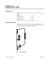
General Information
The NMU supervises and monitors radio performance for and acts as a network element
of a network management system (NMS). One version of the NMU, P/N MLN7481,
operates using P4 routing protocol and proprietary management communications. A
recent version, P/N 8050538-00, operates in Ethernet networks using internet protocol
(IP) routing and simple network management protocol (SNMP) communications. The
NMU board mounts on the ACU (Section 3-7).
The MLN7481 normally ships as a option with its associated hardware (MLN1532).
NMU MLN7481C, or later, ships with systems within loop-protected networks.
The CM SNMP option includes the 8050538-00 NMU that Appendix G details. This
NMU allows radio management with any SNMP
v1
-capable management application.
Functional Description
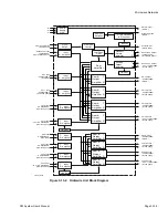
NMU operation controls network management communication using its real-time
operating system. Update the OS from any Telescan network manager or mediation
device. Operation includes the following (Figure 3-15-1):
•
Collects node summary data from the equipment, time and date
stamps it, and forwards it to the NMS master.
•
Monitors parity errors and calculates BER and errored seconds.
•
Allows local access through an RS-232 port at 9.6 kbps, 8, N, 1.
•
Communicates with the NMS through a digital bridge using four
wire RS-485 or an RS-422 interface. The data is asynchronous at
19.2 kbps, 8, O (odd), 1.
•
Supports software download through the NMS.
•
Permits access of NMS over the embedded overhead without sacri-
ficing system performance.
•
Monitors NMU power and performance.
•
Controls the communication bridge from ACU and embedded over-
head channel.
Section 3-15
Network Management Unit (NMU)
Summary of Contents for CM7
Page 2: ......
Page 4: ...Page iv 5 04 05 CM7 8 100Base T System User s Manual ...
Page 16: ...Glossary Page xvi CM System Users Manual X Y Z ...
Page 24: ...Microwave Networks CM7 8 100Base T System User s Manual Pagexxiv ...
Page 62: ...Chapter 2 Operation Page 2 18 5 02 05 CM 100Base T System User s Manual ...
Page 64: ...Chapter 3 Module Descriptions Page 3 2 CM7 8 100Base T ...
Page 88: ...Section 3 3 Transmitter Unit Page 3 3 6 CM7 8 System User s Manual ...
Page 96: ...Section 3 5 RF Power Supply Unit Page 3 5 4 CM System User s Manual ...
Page 100: ...Section 3 6 SP Power Supply Unit Page 3 6 4 CM System User s Manual ...
Page 106: ...Section 3 7 Alarm and Control Unit Page 3 7 6 11 18 03 CM 100Base T System User s Manual ...
Page 124: ...Section 3 11 SYNDES Page 3 11 6 CM System User s Manual ...
Page 130: ...Section 3 12 SCU Page 3 12 6 11 18 03 CM 100Base T System User s Manual ...
Page 138: ...Section 3 13 OWU Page 3 13 8 CM System User s Manual ...
Page 150: ...Section 3 15 NMU Page 3 15 6 CM System User s Manual ...
Page 192: ...Chapter 5 Verification Page 5 20 CM System User s Manual ...
Page 194: ...Chapter 6 Maintenance Page 6 2 7 23 03 CM 100Base T System User s Manual ...
Page 224: ...Chapter 6 Maintenance Page 6 32 7 23 03 CM 100Base T System User s Manual ...
Page 226: ...Site Engineering Page 2 CM System User s Manual ...
Page 230: ...Appendix A T I Curves Page A 4 CM7 8 100Base T System User s Manual ...
Page 267: ...Microwave Networks CM System User s Manual PageB 37 ...
Page 268: ...Appendix B QuikLink Page B 38 CM System User s Manual ...
Page 282: ...Appendix D Alarm Codes Page D 6 5 02 05 CM 100Base T System User s Manual ...
Page 290: ...Appendix E Setting Frequency Page E 8 CM7 8 System User s Manual ...
Page 312: ...CM7 8 100Base T System User s Manual Page I 4 Microwave Networks ...

