Microwave Networks
CM System User’s Manual
2/20/04
Page 4-21
Connecting Antennas
Connect antennas to the radio at the top of the branching network that ends with the
waveguide flange at the top rear of the radio.
CAUTION!
Ensure antenna alignment is complete prior to connecting to the radio.
The CM6 radio uses CMR137F waveguide flanges for the antenna connection and E.I.A.
WR137 waveguide. The CM7/8 radio uses CMR112F waveguide flanges and WR112
waveguide. The CM11 radio uses UG39/U type flanges and WR90 waveguide.
Installing flex-waveguide between the radio antenna port and the antenna feed makes
antenna feed placement relative to the radio rack easier, and minimizes waveguide
vibration damage.
When installing waveguide components, do not drop small screws, or any other
obstruction, into the waveguide run from the radio.
Connect the waveguide from the antenna tower to the flange at the top rear of the radio
using 6-32 standard screws.
Proceed to Chapter 5, System Verification.
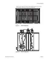
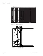
Figures 4-15 and 4-16 show the antenna connections for each configuration.
CAUTION
Figure 4-15.
Antenna Port Connections for NN or HH Radios
Summary of Contents for CM7
Page 2: ......
Page 4: ...Page iv 5 04 05 CM7 8 100Base T System User s Manual ...
Page 16: ...Glossary Page xvi CM System Users Manual X Y Z ...
Page 24: ...Microwave Networks CM7 8 100Base T System User s Manual Pagexxiv ...
Page 62: ...Chapter 2 Operation Page 2 18 5 02 05 CM 100Base T System User s Manual ...
Page 64: ...Chapter 3 Module Descriptions Page 3 2 CM7 8 100Base T ...
Page 88: ...Section 3 3 Transmitter Unit Page 3 3 6 CM7 8 System User s Manual ...
Page 96: ...Section 3 5 RF Power Supply Unit Page 3 5 4 CM System User s Manual ...
Page 100: ...Section 3 6 SP Power Supply Unit Page 3 6 4 CM System User s Manual ...
Page 106: ...Section 3 7 Alarm and Control Unit Page 3 7 6 11 18 03 CM 100Base T System User s Manual ...
Page 124: ...Section 3 11 SYNDES Page 3 11 6 CM System User s Manual ...
Page 130: ...Section 3 12 SCU Page 3 12 6 11 18 03 CM 100Base T System User s Manual ...
Page 138: ...Section 3 13 OWU Page 3 13 8 CM System User s Manual ...
Page 150: ...Section 3 15 NMU Page 3 15 6 CM System User s Manual ...
Page 192: ...Chapter 5 Verification Page 5 20 CM System User s Manual ...
Page 194: ...Chapter 6 Maintenance Page 6 2 7 23 03 CM 100Base T System User s Manual ...
Page 224: ...Chapter 6 Maintenance Page 6 32 7 23 03 CM 100Base T System User s Manual ...
Page 226: ...Site Engineering Page 2 CM System User s Manual ...
Page 230: ...Appendix A T I Curves Page A 4 CM7 8 100Base T System User s Manual ...
Page 267: ...Microwave Networks CM System User s Manual PageB 37 ...
Page 268: ...Appendix B QuikLink Page B 38 CM System User s Manual ...
Page 282: ...Appendix D Alarm Codes Page D 6 5 02 05 CM 100Base T System User s Manual ...
Page 290: ...Appendix E Setting Frequency Page E 8 CM7 8 System User s Manual ...
Page 312: ...CM7 8 100Base T System User s Manual Page I 4 Microwave Networks ...


