Appendix B
QuikLink
Page B-2
CM System User’s Manual
Screen Layout
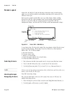
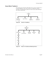
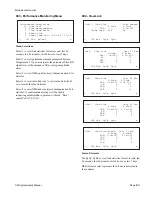
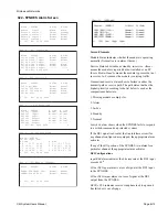
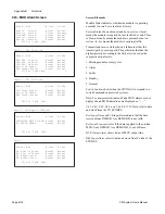
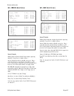
Figures B-1, B-2 (Page B-7), and the following list discusses using screens that may
appear on your computer terminal or performance monitoring device connected to the
radio local access port.
Each screen has a number which allows you to go to that display without scrolling.
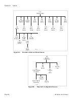
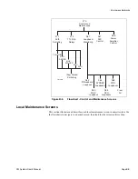
Screens 001 to 007 show the information screen, top-level menus, and performance
statistics. Screens 020 to 040 show alarms and status. Screens 050 to 057 have
configuration settings. And, Screens 070 to 088 have control and maintenance settings.
Screen Control Area
: The lower left corner of the screen denotes which of the five screen
types the terminal displays. Choose from five letters, followed by a three-digit-node
address (000—250, if NMU equipped):
L - denotes a local radio.
R - denotes a remote radio.
c - denotes a co-located radio.
r - denotes the remote terminal of a co-located radio.
N - denotes the NMS network node.
Selecting Screens
1.
Move the cursor into the screen control area (3), to select one of the four screens.
2.
Press 0, then the left arrow key (0,
←
) to select one of the screen views.
3.
Use the Up/Down arrow keys (
↑/↓
) to select L, R, c, or r, then press Enter (
↵
).
NOTE:
Select a screen viewing configuration and press Enter within five seconds between key com-
mands, or the selection function resets.
Aborting Changes
Press ESC to abort any change.
Navigating Screens
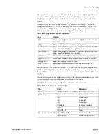
The screen number displays in the lower left corner of the screen (3). There are two
methods of reaching a screen:
1.
Press the Escape key to move from screen to screen through the menu hierarchy, or
2.
Enter the number of the screen you wish to display.
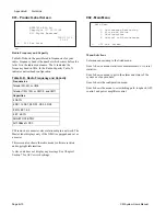
L 002 Esc Select _
Main Menu
>1. Performance Monitoring
2. Alarm and Status
3. Configuration
4. Control and Maintenance
Screen Control Area
Screen Title
Command
Selections,
Information
main
Refresh Indicator
Figure B-1.
Screen 002 – Main Menu
Summary of Contents for CM7
Page 2: ......
Page 4: ...Page iv 5 04 05 CM7 8 100Base T System User s Manual ...
Page 16: ...Glossary Page xvi CM System Users Manual X Y Z ...
Page 24: ...Microwave Networks CM7 8 100Base T System User s Manual Pagexxiv ...
Page 62: ...Chapter 2 Operation Page 2 18 5 02 05 CM 100Base T System User s Manual ...
Page 64: ...Chapter 3 Module Descriptions Page 3 2 CM7 8 100Base T ...
Page 88: ...Section 3 3 Transmitter Unit Page 3 3 6 CM7 8 System User s Manual ...
Page 96: ...Section 3 5 RF Power Supply Unit Page 3 5 4 CM System User s Manual ...
Page 100: ...Section 3 6 SP Power Supply Unit Page 3 6 4 CM System User s Manual ...
Page 106: ...Section 3 7 Alarm and Control Unit Page 3 7 6 11 18 03 CM 100Base T System User s Manual ...
Page 124: ...Section 3 11 SYNDES Page 3 11 6 CM System User s Manual ...
Page 130: ...Section 3 12 SCU Page 3 12 6 11 18 03 CM 100Base T System User s Manual ...
Page 138: ...Section 3 13 OWU Page 3 13 8 CM System User s Manual ...
Page 150: ...Section 3 15 NMU Page 3 15 6 CM System User s Manual ...
Page 192: ...Chapter 5 Verification Page 5 20 CM System User s Manual ...
Page 194: ...Chapter 6 Maintenance Page 6 2 7 23 03 CM 100Base T System User s Manual ...
Page 224: ...Chapter 6 Maintenance Page 6 32 7 23 03 CM 100Base T System User s Manual ...
Page 226: ...Site Engineering Page 2 CM System User s Manual ...
Page 230: ...Appendix A T I Curves Page A 4 CM7 8 100Base T System User s Manual ...
Page 267: ...Microwave Networks CM System User s Manual PageB 37 ...
Page 268: ...Appendix B QuikLink Page B 38 CM System User s Manual ...
Page 282: ...Appendix D Alarm Codes Page D 6 5 02 05 CM 100Base T System User s Manual ...
Page 290: ...Appendix E Setting Frequency Page E 8 CM7 8 System User s Manual ...
Page 312: ...CM7 8 100Base T System User s Manual Page I 4 Microwave Networks ...


