Appendix B
QuikLink
Page B-4
CM System User’s Manual
Monitoring Radio Functions
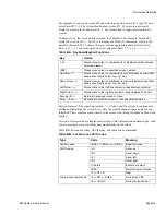
The optional Local Maintenance Terminal (MLN8003A), a VT100/VT220, or an ANSI
equivalent computer terminal provides access to radio monitoring and control screens.
The terminal connects to the local access port. The local access port, a female DB9
RS232 data connector, connects by serial cable to the communications port of the
terminal. Chapter 4, Installation, describes the proper connection for the serial cable. This
cable comes with the optional LMT. Once connected, set the communications port of a
terminal or computer to 9600, 8,N,1 and set the terminal type to VT100.
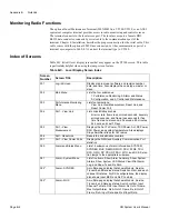
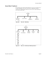
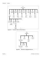
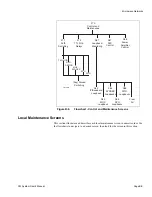
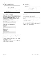
Index of Screens
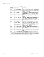
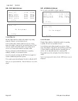
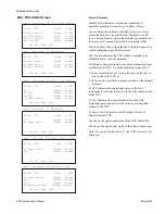
Table B-C lists all local display screens that may appear on the VT100 screen. This table
is particularly helpful when using the jump screen feature.
Table B-C. Local Display Screen Index
Screen
Number
Screen Title
Description
001
Log-in Screen
Displays radio model, software and revision number,
date, and time. Also displays the node type, master or
slave.
002
Main Menu
Lists the four submenus:
1-Performance Monitoring, 2-Alarm and Status,
3-Configuration, and 4-Control and Maintenance.
003
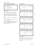
Performance Monitoring
Menu
Lists four selections:
View Link, View Measurement, Reset Link, and
Reset Comm Port.
004
Perf. - View Link
Lists link statistics such as:
bit error rate, frame loss, errored seconds, severely
errored seconds, and frame loss seconds for five
time frames: Last second, 60 seconds, 60 minutes,
24 hours, and Last 7 Days.
005
Perf. - View
Measurement
Displays the Ant. Tx Power, TXU Power, Ant. RX Power,
RXU Power, and system temperature. Also displays
Slope Amplifier stress for CM radios.
006
Perf - Reset Link
Resets the link statistics counters.
007
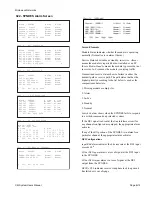
Perf. - View Comm Ports
Displays the NMU and Auxiliary Communication Port
statistics
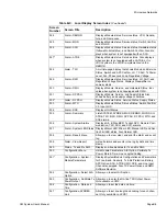
020
Alarm and Status Menu
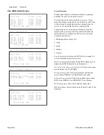
Lists 14 submenus of alarm information: SYSTEM,
SYNDES, MUX, DEMOD, MOD, SCU, ATDE, TXU,
RXU, OWU, SP PSU, RF PSU, WTU, and SCE. Selec-
tion jumps to the appropriate submenu.
021
Alarm - System Menu
Lists five items: Show Alarm Summary, Show System
Alarms, Show System LED Status, View/Print Alarm
Log, and Show Tx and Rx Path.
022*
Alarm - SYNDES
A multiple-page display that shows Module, Service,
Transmit, and Receive status; Switch confirm, and each
channel I/O status. For DS3 configurations, the display
also shows Input BER, and Rx PLL status.
023*
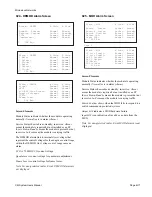
Alarm - MUX
A multiple-page display that shows Module, Service,
Transmit, and Receive status; Switch confirm, Input
Channel Tx Data, DS3 Input Alarm, Rx Out of Frame,
Mux Output Alarm, Rx A Out of Frame, Rx B Out of
Frame, Rx A Input Data, and Rx B Input Data.
Summary of Contents for CM7
Page 2: ......
Page 4: ...Page iv 5 04 05 CM7 8 100Base T System User s Manual ...
Page 16: ...Glossary Page xvi CM System Users Manual X Y Z ...
Page 24: ...Microwave Networks CM7 8 100Base T System User s Manual Pagexxiv ...
Page 62: ...Chapter 2 Operation Page 2 18 5 02 05 CM 100Base T System User s Manual ...
Page 64: ...Chapter 3 Module Descriptions Page 3 2 CM7 8 100Base T ...
Page 88: ...Section 3 3 Transmitter Unit Page 3 3 6 CM7 8 System User s Manual ...
Page 96: ...Section 3 5 RF Power Supply Unit Page 3 5 4 CM System User s Manual ...
Page 100: ...Section 3 6 SP Power Supply Unit Page 3 6 4 CM System User s Manual ...
Page 106: ...Section 3 7 Alarm and Control Unit Page 3 7 6 11 18 03 CM 100Base T System User s Manual ...
Page 124: ...Section 3 11 SYNDES Page 3 11 6 CM System User s Manual ...
Page 130: ...Section 3 12 SCU Page 3 12 6 11 18 03 CM 100Base T System User s Manual ...
Page 138: ...Section 3 13 OWU Page 3 13 8 CM System User s Manual ...
Page 150: ...Section 3 15 NMU Page 3 15 6 CM System User s Manual ...
Page 192: ...Chapter 5 Verification Page 5 20 CM System User s Manual ...
Page 194: ...Chapter 6 Maintenance Page 6 2 7 23 03 CM 100Base T System User s Manual ...
Page 224: ...Chapter 6 Maintenance Page 6 32 7 23 03 CM 100Base T System User s Manual ...
Page 226: ...Site Engineering Page 2 CM System User s Manual ...
Page 230: ...Appendix A T I Curves Page A 4 CM7 8 100Base T System User s Manual ...
Page 267: ...Microwave Networks CM System User s Manual PageB 37 ...
Page 268: ...Appendix B QuikLink Page B 38 CM System User s Manual ...
Page 282: ...Appendix D Alarm Codes Page D 6 5 02 05 CM 100Base T System User s Manual ...
Page 290: ...Appendix E Setting Frequency Page E 8 CM7 8 System User s Manual ...
Page 312: ...CM7 8 100Base T System User s Manual Page I 4 Microwave Networks ...


