Appendix B
QuikLink
Page B-6
CM System User’s Manual
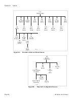
070
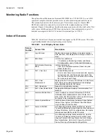
Control and Maintenance
Menu
Lists Path Switching, Loopback, APC, and Power Ampli-
fiers submenus. Transistor-Transistor Logic and Relays.
071
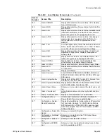
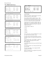
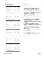
Control - Path Switching
Set path switching for TXU-MOD, RXU-DEMOD, MUX-
SYNDES, SCU, and WTU.
073
TTL I/O & Relays
Displays the TTL input and Relay output control status,
and allows the setting of TTL & Relay output control
points.
081
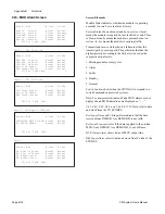
Control - Loopback Menu
Lists IF, MUX, SYNDES, SCU, and WTU loopback sta-
tus and submenus. Clear All resets loopback to normal
operation.
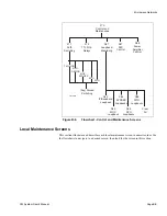
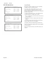
082
Control - IF Loopback
Loop the local equipment and view the status of a local
facility loopback. Not supported on 3DS3 or higher
capacity radios.
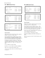
083
Control - MUX Loopback
Loop the local equipment and view the status of a local
facility loopback.
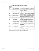
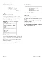
084
Control - 28DS1
SYNDES Loopback
Control - 3DS3–100BaseT
Screens are also shown.
Select local or remote channels, individually or all at
once. To monitor individual channel changes, enter the
channel number. To monitor all channels at once, enter
99 and the screen will display <all>. Screen 84 also
allows you to monitor and change the loopback status
from local to remote equipment.
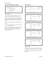
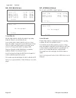
085
Control - SCU Loopback
Loop the local equipment and view the status of a local
facility loopback.
086
Control - WTU Loopback
Loop the local equipment and view the status of a local
facility loopback.
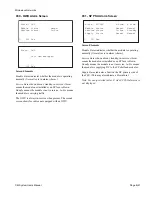
087
Control - APC Manual
Turn APC Manual Mode On/Off, or return to the Auto
Mode.
088
Control - Power Amplifiers
Turn the power amplifiers On or Off for both A and B
radios. Not available on CM11.
* Not all screen selections are available for use with each radio configuration, capacity, or frequency
band. Review specific screen explanations for individual radio applicability.
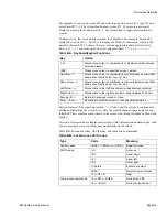
Table B-C. Local Display Screen Index
(Continued)
Screen
Number
Screen Title
Description
Summary of Contents for CM7
Page 2: ......
Page 4: ...Page iv 5 04 05 CM7 8 100Base T System User s Manual ...
Page 16: ...Glossary Page xvi CM System Users Manual X Y Z ...
Page 24: ...Microwave Networks CM7 8 100Base T System User s Manual Pagexxiv ...
Page 62: ...Chapter 2 Operation Page 2 18 5 02 05 CM 100Base T System User s Manual ...
Page 64: ...Chapter 3 Module Descriptions Page 3 2 CM7 8 100Base T ...
Page 88: ...Section 3 3 Transmitter Unit Page 3 3 6 CM7 8 System User s Manual ...
Page 96: ...Section 3 5 RF Power Supply Unit Page 3 5 4 CM System User s Manual ...
Page 100: ...Section 3 6 SP Power Supply Unit Page 3 6 4 CM System User s Manual ...
Page 106: ...Section 3 7 Alarm and Control Unit Page 3 7 6 11 18 03 CM 100Base T System User s Manual ...
Page 124: ...Section 3 11 SYNDES Page 3 11 6 CM System User s Manual ...
Page 130: ...Section 3 12 SCU Page 3 12 6 11 18 03 CM 100Base T System User s Manual ...
Page 138: ...Section 3 13 OWU Page 3 13 8 CM System User s Manual ...
Page 150: ...Section 3 15 NMU Page 3 15 6 CM System User s Manual ...
Page 192: ...Chapter 5 Verification Page 5 20 CM System User s Manual ...
Page 194: ...Chapter 6 Maintenance Page 6 2 7 23 03 CM 100Base T System User s Manual ...
Page 224: ...Chapter 6 Maintenance Page 6 32 7 23 03 CM 100Base T System User s Manual ...
Page 226: ...Site Engineering Page 2 CM System User s Manual ...
Page 230: ...Appendix A T I Curves Page A 4 CM7 8 100Base T System User s Manual ...
Page 267: ...Microwave Networks CM System User s Manual PageB 37 ...
Page 268: ...Appendix B QuikLink Page B 38 CM System User s Manual ...
Page 282: ...Appendix D Alarm Codes Page D 6 5 02 05 CM 100Base T System User s Manual ...
Page 290: ...Appendix E Setting Frequency Page E 8 CM7 8 System User s Manual ...
Page 312: ...CM7 8 100Base T System User s Manual Page I 4 Microwave Networks ...

