Appendix B
QuikLink
Page B-18
CM System Users Manual
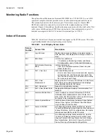
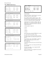
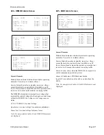
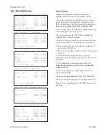
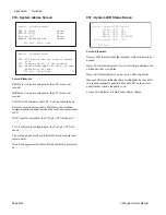
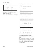
026 - SCU Alarm Screen
Screen Elements
Module Status indicates whether the module is operating
normally (
Normal
) or is in alarm (
Alarm
.)
Service Status shows absent, standby, in-service.
Absent
means the module is required but not installed or an SP fuse
is blown.
Standby
means the module is present but not in
service.
In-Svc
means the module is carrying traffic.
Hardware Status
shows that the hardware is operating
normally (Normal) or is in alarm (Alarm).
Switch Confirm
shows when the MUX fails to respond to a
switch command on protected systems.
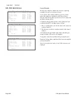
The second screen shown displays for radios without an SCU
Note: For non-protected radios, B side SCU alarms are not dis-
played.
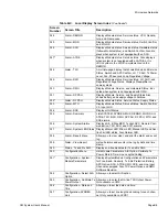
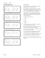
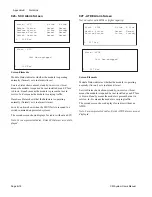
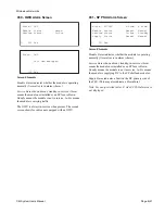
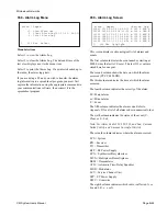
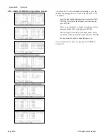
027 - ATDE Alarm Screen
Not on radios with 3DS3 or higher capacity.
Screen Elements
Module Status indicates whether the module is operating
normally (
Normal
) or is in alarm (
Alarm
.)
Service Status shows absent, standby, in-service.
Absent
means the module is required but not installed or an SP fuse
is blown.
Standby
means the module is present but not in
service.
In-Svc
means the module is carrying traffic.
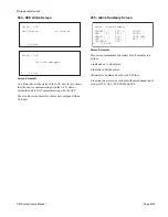
The second screen shown displays for radios without an
ATDE.
Note: For non-protected radios, B side ATDE alarms are not
displayed.
L 026 Esc
Alarm - SCU A Side B Side
Module Status: Normal Normal
Service Status: In-Svc Standby
Hardware Status: Normal Normal
Switch Confirm: Normal Normal
Alarm - SCU
Unit Non-equipped
L 026 Esc
L 027 Esc
Alarm - ATDE A Side B Side
Module Status: Normal Normal
Service Status: In-Svc Standby
L 027 Esc
Alarm - ATDE
Unit Non-equipped
Summary of Contents for CM7
Page 2: ......
Page 4: ...Page iv 5 04 05 CM7 8 100Base T System User s Manual ...
Page 16: ...Glossary Page xvi CM System Users Manual X Y Z ...
Page 24: ...Microwave Networks CM7 8 100Base T System User s Manual Pagexxiv ...
Page 62: ...Chapter 2 Operation Page 2 18 5 02 05 CM 100Base T System User s Manual ...
Page 64: ...Chapter 3 Module Descriptions Page 3 2 CM7 8 100Base T ...
Page 88: ...Section 3 3 Transmitter Unit Page 3 3 6 CM7 8 System User s Manual ...
Page 96: ...Section 3 5 RF Power Supply Unit Page 3 5 4 CM System User s Manual ...
Page 100: ...Section 3 6 SP Power Supply Unit Page 3 6 4 CM System User s Manual ...
Page 106: ...Section 3 7 Alarm and Control Unit Page 3 7 6 11 18 03 CM 100Base T System User s Manual ...
Page 124: ...Section 3 11 SYNDES Page 3 11 6 CM System User s Manual ...
Page 130: ...Section 3 12 SCU Page 3 12 6 11 18 03 CM 100Base T System User s Manual ...
Page 138: ...Section 3 13 OWU Page 3 13 8 CM System User s Manual ...
Page 150: ...Section 3 15 NMU Page 3 15 6 CM System User s Manual ...
Page 192: ...Chapter 5 Verification Page 5 20 CM System User s Manual ...
Page 194: ...Chapter 6 Maintenance Page 6 2 7 23 03 CM 100Base T System User s Manual ...
Page 224: ...Chapter 6 Maintenance Page 6 32 7 23 03 CM 100Base T System User s Manual ...
Page 226: ...Site Engineering Page 2 CM System User s Manual ...
Page 230: ...Appendix A T I Curves Page A 4 CM7 8 100Base T System User s Manual ...
Page 267: ...Microwave Networks CM System User s Manual PageB 37 ...
Page 268: ...Appendix B QuikLink Page B 38 CM System User s Manual ...
Page 282: ...Appendix D Alarm Codes Page D 6 5 02 05 CM 100Base T System User s Manual ...
Page 290: ...Appendix E Setting Frequency Page E 8 CM7 8 System User s Manual ...
Page 312: ...CM7 8 100Base T System User s Manual Page I 4 Microwave Networks ...

