Appendix B
QuikLink
Page B-22
CM System Users Manual
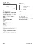
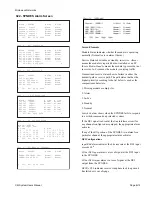
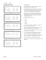
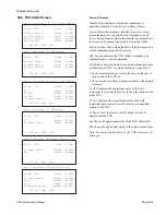
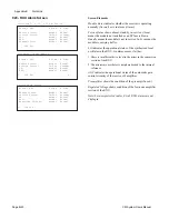
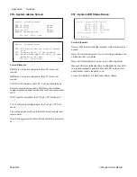
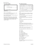
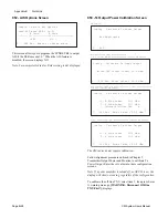
032 - RF PSU Alarm Screen
Screen Elements
Module Status
indicates whether the module is operating
normally (
Normal
) or is in alarm (
Alarm
.)
Service Status
shows absent, standby, in-service.
Absent
means the module not installed or an SP fuse is blown.
Standby
means the module is not in service.
In-Svc
means the
module is supplying DC to the RF shelf and modules.
Supply Status
indicates a fault on the DC primary side of the
PSU. (This may also indicate a blown fuse.)
Note: For non-protected radios, B side RF PSU alarms are not
displayed.
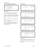
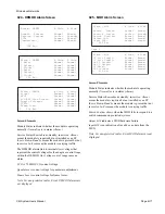
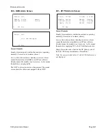
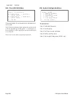
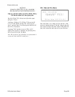
033 - WTU Alarm Screen
Screen Elements
Module Status
indicates whether the module is operating
normally (
Normal
) or is in alarm (
Alarm
.)
Service Status
shows absent, standby, in-service.
Absent
means the module is required but not installed or an SP fuse
is blown.
Standby
means the module is present but not in
service.
In-Svc
means the module is carrying traffic.
Switch Confirm
shows when the MUX fails to respond to a
switch command on protected systems.
Ch Input LOS
indicates a loss of signal for the digital line
input to the WTU.
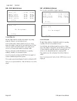
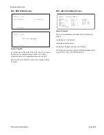
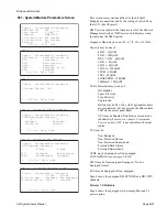
The second screen shows for radios not equipped with a
WTU.
Note: B side WTU alarms do not display in non-protected ra-
dios.
L 032 Esc PgUp PgDn
Alarm - RF PSU A Side B Side
Module Status: Normal Normal
Service Status: In-Svc In-Svc
Supply Status: Normal Normal
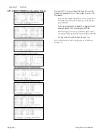
L 032 Esc PgUp
Alarm - RF PSU A Side B Side
Battery: Normal Normal
+12.0 Volt Supply: Normal Normal
-6.0 Volt Supply: Normal Normal
Page 2
L 033 Esc
Alarm - WTU A Side B Side
Module Status: Normal Normal
Service Status: In-Svc Standby
Switch Confirm: Normal Normal
Ch.Input LOS: Normal Normal
L 033 Esc
Alarm - WTU
Unit Non-equipped
Summary of Contents for CM7
Page 2: ......
Page 4: ...Page iv 5 04 05 CM7 8 100Base T System User s Manual ...
Page 16: ...Glossary Page xvi CM System Users Manual X Y Z ...
Page 24: ...Microwave Networks CM7 8 100Base T System User s Manual Pagexxiv ...
Page 62: ...Chapter 2 Operation Page 2 18 5 02 05 CM 100Base T System User s Manual ...
Page 64: ...Chapter 3 Module Descriptions Page 3 2 CM7 8 100Base T ...
Page 88: ...Section 3 3 Transmitter Unit Page 3 3 6 CM7 8 System User s Manual ...
Page 96: ...Section 3 5 RF Power Supply Unit Page 3 5 4 CM System User s Manual ...
Page 100: ...Section 3 6 SP Power Supply Unit Page 3 6 4 CM System User s Manual ...
Page 106: ...Section 3 7 Alarm and Control Unit Page 3 7 6 11 18 03 CM 100Base T System User s Manual ...
Page 124: ...Section 3 11 SYNDES Page 3 11 6 CM System User s Manual ...
Page 130: ...Section 3 12 SCU Page 3 12 6 11 18 03 CM 100Base T System User s Manual ...
Page 138: ...Section 3 13 OWU Page 3 13 8 CM System User s Manual ...
Page 150: ...Section 3 15 NMU Page 3 15 6 CM System User s Manual ...
Page 192: ...Chapter 5 Verification Page 5 20 CM System User s Manual ...
Page 194: ...Chapter 6 Maintenance Page 6 2 7 23 03 CM 100Base T System User s Manual ...
Page 224: ...Chapter 6 Maintenance Page 6 32 7 23 03 CM 100Base T System User s Manual ...
Page 226: ...Site Engineering Page 2 CM System User s Manual ...
Page 230: ...Appendix A T I Curves Page A 4 CM7 8 100Base T System User s Manual ...
Page 267: ...Microwave Networks CM System User s Manual PageB 37 ...
Page 268: ...Appendix B QuikLink Page B 38 CM System User s Manual ...
Page 282: ...Appendix D Alarm Codes Page D 6 5 02 05 CM 100Base T System User s Manual ...
Page 290: ...Appendix E Setting Frequency Page E 8 CM7 8 System User s Manual ...
Page 312: ...CM7 8 100Base T System User s Manual Page I 4 Microwave Networks ...

