Appendix B
QuikLink
Page B-24
CM System Users Manual
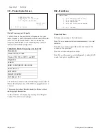
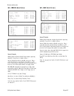
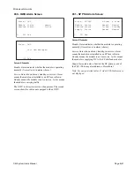
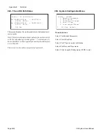
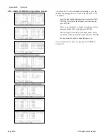
036 - System Alarms Screen
Screen Elements
BER Major
is an error rate greater than 10
-3
errors per
second.
BER Minor
is an error rate greater than 10
-9
errors per
second.
Tx HIGH APC
indicates that APC is off, but should be on.
Remote Communication
shows a failure in the overhead
communications channel between the local and remote radio
ACU.
If APC option is disabled, the
Tx High APC
field shows “– –
– – –”.
For 7/8 GHz radio configurations, the
Tx High APC
field
shows “– – – – –”.
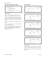
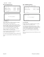
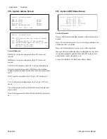
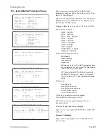
The second page describes problems between modules and
remote units.
Note: For non-protected radios, B side alarms are presented
as “– – – – –”.
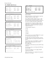
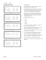
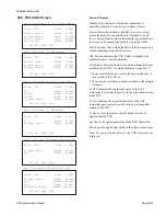
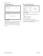
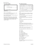
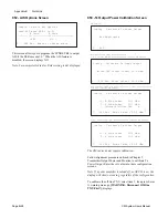
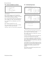
037 - System LED Status Screen
Screen Elements
Normal LED
indicates that the summary status alarms are not
needed.
Major LED
alarm indicates a service-affecting condition of an
on-line unit that is in alarm.
Minor LED
alarm indicates a non service-affecting alarm.
Manual LED
alarm indicates that a switch plane has been left
in a locked (manual) condition.
Manual LED
on the access
panel flashes when a loopback is on.
Section Fail
indicates a remote radio Major Alarm.
L 036 Esc PgUp PgDn
Alarm - System Alarms
BER (A Side): Major
BER (B Side): Minor
Tx High APC: Alarm
Remote Communication: Normal
Alarm - System Alarms
TXU: APC option not the same at remote
site.
SCU: Remote end SCU is not present.
Sys: Remote node does not have the same
protection as local.
L 036 Esc PgUp PgDn O
L 037 Esc
Alarm - System LED Status
Normal LED: ON
Major LED: OFF
Minor LED: OFF
Manual LED: BLINKING
Section Fail LED: OFF
Summary of Contents for CM7
Page 2: ......
Page 4: ...Page iv 5 04 05 CM7 8 100Base T System User s Manual ...
Page 16: ...Glossary Page xvi CM System Users Manual X Y Z ...
Page 24: ...Microwave Networks CM7 8 100Base T System User s Manual Pagexxiv ...
Page 62: ...Chapter 2 Operation Page 2 18 5 02 05 CM 100Base T System User s Manual ...
Page 64: ...Chapter 3 Module Descriptions Page 3 2 CM7 8 100Base T ...
Page 88: ...Section 3 3 Transmitter Unit Page 3 3 6 CM7 8 System User s Manual ...
Page 96: ...Section 3 5 RF Power Supply Unit Page 3 5 4 CM System User s Manual ...
Page 100: ...Section 3 6 SP Power Supply Unit Page 3 6 4 CM System User s Manual ...
Page 106: ...Section 3 7 Alarm and Control Unit Page 3 7 6 11 18 03 CM 100Base T System User s Manual ...
Page 124: ...Section 3 11 SYNDES Page 3 11 6 CM System User s Manual ...
Page 130: ...Section 3 12 SCU Page 3 12 6 11 18 03 CM 100Base T System User s Manual ...
Page 138: ...Section 3 13 OWU Page 3 13 8 CM System User s Manual ...
Page 150: ...Section 3 15 NMU Page 3 15 6 CM System User s Manual ...
Page 192: ...Chapter 5 Verification Page 5 20 CM System User s Manual ...
Page 194: ...Chapter 6 Maintenance Page 6 2 7 23 03 CM 100Base T System User s Manual ...
Page 224: ...Chapter 6 Maintenance Page 6 32 7 23 03 CM 100Base T System User s Manual ...
Page 226: ...Site Engineering Page 2 CM System User s Manual ...
Page 230: ...Appendix A T I Curves Page A 4 CM7 8 100Base T System User s Manual ...
Page 267: ...Microwave Networks CM System User s Manual PageB 37 ...
Page 268: ...Appendix B QuikLink Page B 38 CM System User s Manual ...
Page 282: ...Appendix D Alarm Codes Page D 6 5 02 05 CM 100Base T System User s Manual ...
Page 290: ...Appendix E Setting Frequency Page E 8 CM7 8 System User s Manual ...
Page 312: ...CM7 8 100Base T System User s Manual Page I 4 Microwave Networks ...

