Microwave Networks
CM System Users Manual
Page B-25
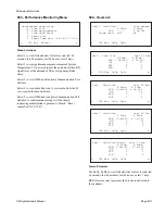
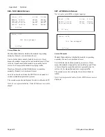
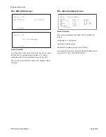
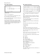
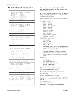
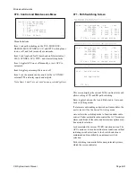
038 - Alarm Log Menu
Menu Selections
Select 1 to view the Alarm Log.
Select 2 to clear the Alarm Log. The date and time of the
last clear displays next to the menu item.
Select 3 to print the Alarm Log. If a printer is hooked up to
the radio, the alarm log prints.
If you are using a PC and you wish to transfer the alarm
log information to a spreadsheet program, you must first
capture the information using the appropriate commands in
your communications software, then convert it to the
spreadsheet program.
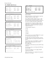
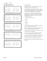
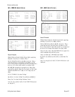
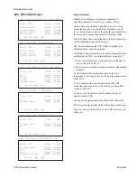
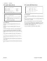
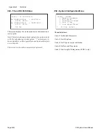
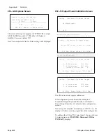
039 - Alarm Log Screen
This screen displays a chronological list of alarms and
events.
The first column indicates the event number, starting at
00000, since the last ACU reset. The last 512 events are
stored here for one year.
The second column shows the date on which the alarm
occurred (YYYY-MM-DD).
The third column indicates the time at which the alarm
occurred.
The fourth column indicates the severity of the alarm:
M = Major alarm
m = Minor alarm
E = Event
The fifth column indicates the alarm code. Refer to
Appendix D
for a list of all alarm codes in numerical order.
The sixth column indicates the status of the event (C -
Clear, or S - Set).
Note: For Alarm Codes 119, 120, 121, and 166, C means
Failed Switch, and S means Successful Switch.
The seventh column indicates where the alarm occurred.
SYS = System
RX = Receiver
TX = Transmitter
RFP = RF Power Supply
SYN = Synthesizer/Desynthesizer
MUX = Multiplexer/Demultiplexer
DEM = Demodulator
ATD = Automatic Time-Delay Equalizer
MOD = Modulator
SCU = Service Channel Unit
SPP = SP Power Supply
OWU = Orderwire
The eighth column indicates which radio is affected: A or
B, and L, R, c, r, or N.
L 038 Esc Select_
Alarm - Report
>1. View Alarm Log
2. Clear Alarm Log[93-11-10 09:00]
3. Print Alarm Log
L 039 Esc PgUp PgDn
Alarm - Report >Bottom Top
00060 1999-01-08 06:55:11 E 069 S MUX A
00061 1999-01-09 08:00:23 m 069 S DEM B
00062 1999-01-09 18:34:12 m 073 S MUX B
00063 1999-01-09 22:02:42 E 119 S SYN B
00064 1999-01-10 12:38:33 M 116 C MUX B
00065 1999-01-10 13:34:56 m 073 S MUX A
Summary of Contents for CM7
Page 2: ......
Page 4: ...Page iv 5 04 05 CM7 8 100Base T System User s Manual ...
Page 16: ...Glossary Page xvi CM System Users Manual X Y Z ...
Page 24: ...Microwave Networks CM7 8 100Base T System User s Manual Pagexxiv ...
Page 62: ...Chapter 2 Operation Page 2 18 5 02 05 CM 100Base T System User s Manual ...
Page 64: ...Chapter 3 Module Descriptions Page 3 2 CM7 8 100Base T ...
Page 88: ...Section 3 3 Transmitter Unit Page 3 3 6 CM7 8 System User s Manual ...
Page 96: ...Section 3 5 RF Power Supply Unit Page 3 5 4 CM System User s Manual ...
Page 100: ...Section 3 6 SP Power Supply Unit Page 3 6 4 CM System User s Manual ...
Page 106: ...Section 3 7 Alarm and Control Unit Page 3 7 6 11 18 03 CM 100Base T System User s Manual ...
Page 124: ...Section 3 11 SYNDES Page 3 11 6 CM System User s Manual ...
Page 130: ...Section 3 12 SCU Page 3 12 6 11 18 03 CM 100Base T System User s Manual ...
Page 138: ...Section 3 13 OWU Page 3 13 8 CM System User s Manual ...
Page 150: ...Section 3 15 NMU Page 3 15 6 CM System User s Manual ...
Page 192: ...Chapter 5 Verification Page 5 20 CM System User s Manual ...
Page 194: ...Chapter 6 Maintenance Page 6 2 7 23 03 CM 100Base T System User s Manual ...
Page 224: ...Chapter 6 Maintenance Page 6 32 7 23 03 CM 100Base T System User s Manual ...
Page 226: ...Site Engineering Page 2 CM System User s Manual ...
Page 230: ...Appendix A T I Curves Page A 4 CM7 8 100Base T System User s Manual ...
Page 267: ...Microwave Networks CM System User s Manual PageB 37 ...
Page 268: ...Appendix B QuikLink Page B 38 CM System User s Manual ...
Page 282: ...Appendix D Alarm Codes Page D 6 5 02 05 CM 100Base T System User s Manual ...
Page 290: ...Appendix E Setting Frequency Page E 8 CM7 8 System User s Manual ...
Page 312: ...CM7 8 100Base T System User s Manual Page I 4 Microwave Networks ...

