Appendix B
QuikLink
Page B-28
CM System Users Manual
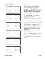
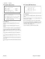
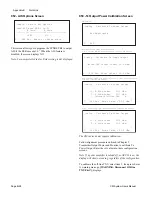
052 - AIS Options Screen
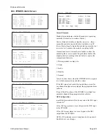
This screen allows you to program the SYNDES Rx to output
AIS if the BER exceeds 10
-3
. When the AIS feature is
disabled, the screen displays NO.
Note: For non-protected radios, B side setting is not displayed.
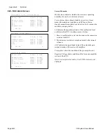
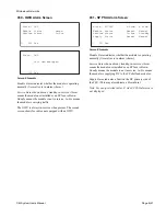
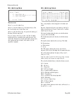
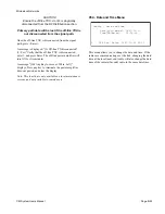
053 -Tx Output Power Calibration Screen
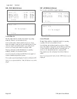
The CM radios do not require calibration.
Follow alignment procedure outlined in Chapter 5,
Transmitter Output Power and Monitor, to calibrate Tx
Power Output. Enter the set value into these configuration
screens.
Note: If a power amplifier is turned off, or APC H is on, the
display will show no reading, regardless of the configuration.
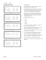
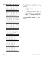
To calibrate the off-line TXU, select item 3, then press Enter.
A warning message,
[WARNING: Disconnect Off-line
TXU First!],
displays.
L 052 Esc Enter to change state
Config - Select AIS Options
Send AIS when BER > 1e-3?
A Side B Side
--------------------------------------
>YES NO
L 053 Esc Enter Value : 00.0 dBm
Config - Calibrate Tx Power Output
Online TXU Output Power: 23.5 dBm
Config - Calibrate Tx Power Output
>1. A Side Power 23.5 dBm
2. B Side Power 21.3 dBm
3. Calibrate Off-line TXU A
[ ]
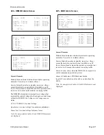
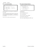
L 053 Esc Enter Value : 00.0 dBm
Config - Calibrate Tx Power Output
>1. A Side Power 23.5 dBm
2. B Side Power 21.3 dBm
[ ]
L 053 Esc Enter Value : 00.0 dBm
Config - Calibrate Tx Power Output
Not Applicable
L 053
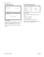
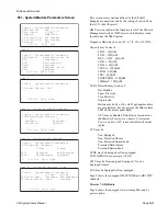
Non-Protected (NN) Configuration
2,6,& 10-GHz HH/HS Configuration (except CM radio)
Hot-Standby (HH) and Space Diversity (HS) Configuration
7/8 GHz (except CM radio)
Freq. Diversity (FF) Configuration (except CM radio)
CM radios
Summary of Contents for CM7
Page 2: ......
Page 4: ...Page iv 5 04 05 CM7 8 100Base T System User s Manual ...
Page 16: ...Glossary Page xvi CM System Users Manual X Y Z ...
Page 24: ...Microwave Networks CM7 8 100Base T System User s Manual Pagexxiv ...
Page 62: ...Chapter 2 Operation Page 2 18 5 02 05 CM 100Base T System User s Manual ...
Page 64: ...Chapter 3 Module Descriptions Page 3 2 CM7 8 100Base T ...
Page 88: ...Section 3 3 Transmitter Unit Page 3 3 6 CM7 8 System User s Manual ...
Page 96: ...Section 3 5 RF Power Supply Unit Page 3 5 4 CM System User s Manual ...
Page 100: ...Section 3 6 SP Power Supply Unit Page 3 6 4 CM System User s Manual ...
Page 106: ...Section 3 7 Alarm and Control Unit Page 3 7 6 11 18 03 CM 100Base T System User s Manual ...
Page 124: ...Section 3 11 SYNDES Page 3 11 6 CM System User s Manual ...
Page 130: ...Section 3 12 SCU Page 3 12 6 11 18 03 CM 100Base T System User s Manual ...
Page 138: ...Section 3 13 OWU Page 3 13 8 CM System User s Manual ...
Page 150: ...Section 3 15 NMU Page 3 15 6 CM System User s Manual ...
Page 192: ...Chapter 5 Verification Page 5 20 CM System User s Manual ...
Page 194: ...Chapter 6 Maintenance Page 6 2 7 23 03 CM 100Base T System User s Manual ...
Page 224: ...Chapter 6 Maintenance Page 6 32 7 23 03 CM 100Base T System User s Manual ...
Page 226: ...Site Engineering Page 2 CM System User s Manual ...
Page 230: ...Appendix A T I Curves Page A 4 CM7 8 100Base T System User s Manual ...
Page 267: ...Microwave Networks CM System User s Manual PageB 37 ...
Page 268: ...Appendix B QuikLink Page B 38 CM System User s Manual ...
Page 282: ...Appendix D Alarm Codes Page D 6 5 02 05 CM 100Base T System User s Manual ...
Page 290: ...Appendix E Setting Frequency Page E 8 CM7 8 System User s Manual ...
Page 312: ...CM7 8 100Base T System User s Manual Page I 4 Microwave Networks ...


