Appendix B
QuikLink
Page B-32
CM System Users Manual
073 - TTL and Relay I/O Status Screens
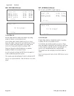
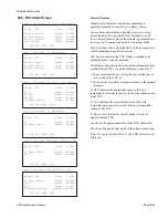
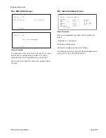
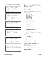
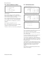
TTL I/O Status
This screen shows radio TTL input status and output control
points.
Point
indicates the four (NMU not equipped) or eight (NMU
equipped) TTL input points available for external connection.
Input Status
displays the specific TTL logic value of
individual input points.
Output Control
displays the specific logic value of individual
TTL output control points (0 = Off, 1 = On).
Note: This screen is not available on radios not equipped
with an NMU.
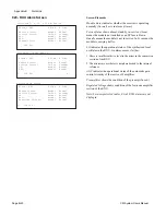
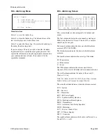
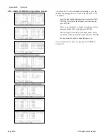
Relay I/O Status
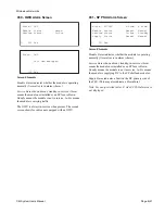
This screen shows radio output control points status. Page 2
shows output control points status and allows the setting of
individual relay output control points
Point
indicates the four relay control points available for
external connection.
Output Control
displays the specific logic value of individual
relay output control points (0 = Off, 1 = On).
Remote TTL In
displays the status of the relay output control
point links to the cross hop TTL input. This line displays the
remote TTL input point number if the relay control point
links to a remote input, or displays No if it doesn’t link to
remote TTL input.
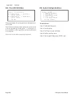
Output
Relay output setting. Rmt - remote control: On - local
set on, Off - local set off.
Ctrl - TTL I/O
Point: 1 2 3 4 5 6 7 8
Input Status: 0 1 0 1 0 1 1 0
Output Control: 1 0 1 0
[Press Enter to Change Output ]
L 073 Esc PgUp PgDn o
Page 1: TTL I/O Status for NMU Equipped Radio
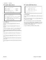
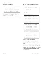
Ctrl - TTL I/O
Point: 1 2 3 4 5 6 7 8
Input Status: 0 1 0 1 0 1 1 0
Output Control: 1 0 1 0
[ Output: 1 0 1 0 ]
L 073 Esc o
Page 1: Relay I/O Status
Ctrl - Relays
Point: 1 2 3 4
Output Control: On Off Off Off
Remote TTL In: 5 6 No No
[Press Enter to Change Output ]
L 073 Esc PgUp PgDn
Ctrl - Relays
Point: 1 2 3 4
Output Control: On On Off Off
Remote TTL In: 5 6 No No
[ Output: Rmt Rmt On Off ]
L 073 Esc Up Dn L R <Enter>
Page 2: TTL I/O Status for NMU Equipped Radio
Page 2: Relay I/O Status
Summary of Contents for CM7
Page 2: ......
Page 4: ...Page iv 5 04 05 CM7 8 100Base T System User s Manual ...
Page 16: ...Glossary Page xvi CM System Users Manual X Y Z ...
Page 24: ...Microwave Networks CM7 8 100Base T System User s Manual Pagexxiv ...
Page 62: ...Chapter 2 Operation Page 2 18 5 02 05 CM 100Base T System User s Manual ...
Page 64: ...Chapter 3 Module Descriptions Page 3 2 CM7 8 100Base T ...
Page 88: ...Section 3 3 Transmitter Unit Page 3 3 6 CM7 8 System User s Manual ...
Page 96: ...Section 3 5 RF Power Supply Unit Page 3 5 4 CM System User s Manual ...
Page 100: ...Section 3 6 SP Power Supply Unit Page 3 6 4 CM System User s Manual ...
Page 106: ...Section 3 7 Alarm and Control Unit Page 3 7 6 11 18 03 CM 100Base T System User s Manual ...
Page 124: ...Section 3 11 SYNDES Page 3 11 6 CM System User s Manual ...
Page 130: ...Section 3 12 SCU Page 3 12 6 11 18 03 CM 100Base T System User s Manual ...
Page 138: ...Section 3 13 OWU Page 3 13 8 CM System User s Manual ...
Page 150: ...Section 3 15 NMU Page 3 15 6 CM System User s Manual ...
Page 192: ...Chapter 5 Verification Page 5 20 CM System User s Manual ...
Page 194: ...Chapter 6 Maintenance Page 6 2 7 23 03 CM 100Base T System User s Manual ...
Page 224: ...Chapter 6 Maintenance Page 6 32 7 23 03 CM 100Base T System User s Manual ...
Page 226: ...Site Engineering Page 2 CM System User s Manual ...
Page 230: ...Appendix A T I Curves Page A 4 CM7 8 100Base T System User s Manual ...
Page 267: ...Microwave Networks CM System User s Manual PageB 37 ...
Page 268: ...Appendix B QuikLink Page B 38 CM System User s Manual ...
Page 282: ...Appendix D Alarm Codes Page D 6 5 02 05 CM 100Base T System User s Manual ...
Page 290: ...Appendix E Setting Frequency Page E 8 CM7 8 System User s Manual ...
Page 312: ...CM7 8 100Base T System User s Manual Page I 4 Microwave Networks ...

