CM System User’s Manual
6/14/02
Page F-3
Microwave Networks
The SNMP NMU (Network Management Unit)
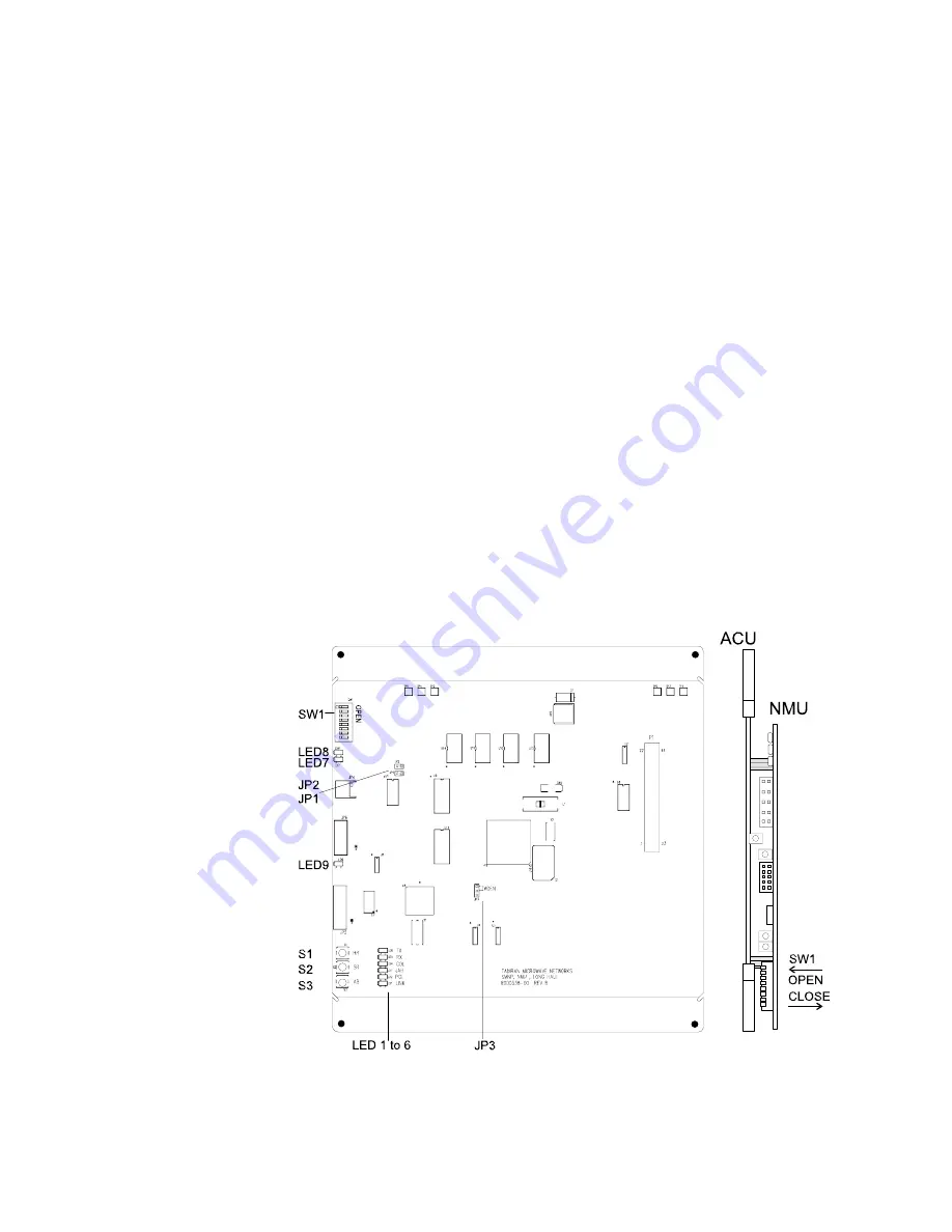
The SNMP NMU (Figure F-2) mounts on the ACU and acts as the SNMP agent. The
NMU collects management data from its radio and, on request from an SNMP
manager, distributes the data through the network to the manager. The NMU automati-
cally sends critical radio errors, called traps, to the SNMP manager.
Traps are the standard mechanism of SNMP for unsolicited reports from network
elements to the network manager. Traps store variable data and static textual informa-
tion in the SNMP NMU. Successive traps with same textual information need only
transfer the variable data.
Each SNMP NMU acts as a multi-homed device. That is, each radio has two IP inter-
faces, so two IP addresses. One interface is the Ethernet interface at 10 Mbps, and the
other is the over-the-air interface of the radio overhead channel at 64 kbps. The over-
the-air interface transports status and command data over the microwave link. The IP
address of the Ethernet interface is also the address of the SNMP NMU.
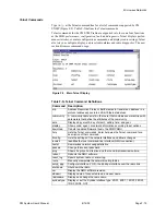
Major components of the SNMP NMU to note are the nine LEDs (Table F-D), three
push-button switches (Table F-E), and three jumpers (Table F-F). Two megabytes of
flash memory stores the SNMP system parameters and variables. NMU software may
be downloaded to the board through the network using the TFTP service (see your
computer utilities documentation).
Position 6 of eight-position dip switch SW1 toggles communication to the local access
port between the ACU and NMU. Close SW1-6 to communicate with the NMU. Open
SW1-6 to communicate with the ACU. SW1-6 should remain closed with all other
positions open for normal operation.
Figure F-2. SNMP NMU Card
Summary of Contents for CM7
Page 2: ......
Page 4: ...Page iv 5 04 05 CM7 8 100Base T System User s Manual ...
Page 16: ...Glossary Page xvi CM System Users Manual X Y Z ...
Page 24: ...Microwave Networks CM7 8 100Base T System User s Manual Pagexxiv ...
Page 62: ...Chapter 2 Operation Page 2 18 5 02 05 CM 100Base T System User s Manual ...
Page 64: ...Chapter 3 Module Descriptions Page 3 2 CM7 8 100Base T ...
Page 88: ...Section 3 3 Transmitter Unit Page 3 3 6 CM7 8 System User s Manual ...
Page 96: ...Section 3 5 RF Power Supply Unit Page 3 5 4 CM System User s Manual ...
Page 100: ...Section 3 6 SP Power Supply Unit Page 3 6 4 CM System User s Manual ...
Page 106: ...Section 3 7 Alarm and Control Unit Page 3 7 6 11 18 03 CM 100Base T System User s Manual ...
Page 124: ...Section 3 11 SYNDES Page 3 11 6 CM System User s Manual ...
Page 130: ...Section 3 12 SCU Page 3 12 6 11 18 03 CM 100Base T System User s Manual ...
Page 138: ...Section 3 13 OWU Page 3 13 8 CM System User s Manual ...
Page 150: ...Section 3 15 NMU Page 3 15 6 CM System User s Manual ...
Page 192: ...Chapter 5 Verification Page 5 20 CM System User s Manual ...
Page 194: ...Chapter 6 Maintenance Page 6 2 7 23 03 CM 100Base T System User s Manual ...
Page 224: ...Chapter 6 Maintenance Page 6 32 7 23 03 CM 100Base T System User s Manual ...
Page 226: ...Site Engineering Page 2 CM System User s Manual ...
Page 230: ...Appendix A T I Curves Page A 4 CM7 8 100Base T System User s Manual ...
Page 267: ...Microwave Networks CM System User s Manual PageB 37 ...
Page 268: ...Appendix B QuikLink Page B 38 CM System User s Manual ...
Page 282: ...Appendix D Alarm Codes Page D 6 5 02 05 CM 100Base T System User s Manual ...
Page 290: ...Appendix E Setting Frequency Page E 8 CM7 8 System User s Manual ...
Page 312: ...CM7 8 100Base T System User s Manual Page I 4 Microwave Networks ...


