CM SNMP
Page F-4
6/14/02
CM System User’s Manual
Layout of a CM SNMP Network
This section describes the typical network layout of CM radios using the SNMP
option. Figure F-3 shows this layout.
The management station, or SNMP manager, sends SNMP get and set requests to the
SNMP agents–each radio NMU. The SNMP NMU answers get and set requests from
the manager as specified by the Microwave-Networks MIB (management information
base).
The MIB contains the common name of each object (which must be unique), the value
of the OID (object IDs, which are hierarchical and must be unique), and the textual
description of the syntax and semantics of the CM radio.
Each radio has two IP addresses: one addresses the Ethernet interface (
IF
1), the address
of its SNMP NMU, and the other the 64 kbps over-the-air interface (
IF
2). The over-
the-air interface transports radio support data, including get and set requests from the
SNMP manager, over the microwave link to other radios addressed in the network
routing tables.
A local connection at the front panel of each radio is available for on-site radio mainte-
nance using the local maintenance terminal (LMT;
see Chapter 6, Sub-section 1.3
).
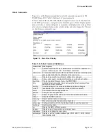
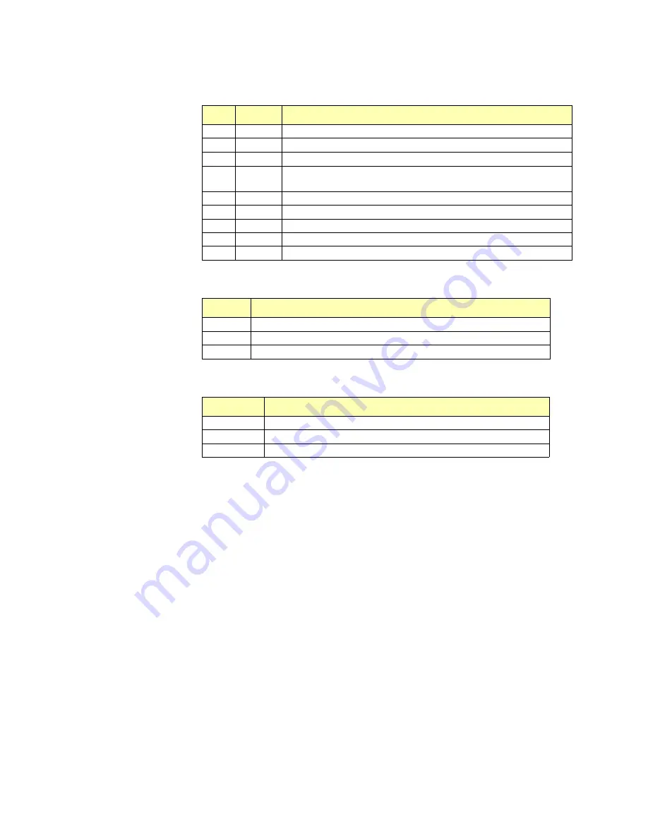
Table F-D. SNMP NMU LED Descriptions
LED
Name
Function
LD1
LINK
Indicates that the Ethernet link is plugged into a valid network
LD2
POL
Polarity Reverse – indicates reversed polarity at the Ethernet Rx
LD3
JAB
Jabber – indicates linking communication has been established
LD4
COL
Collision – indicates that the send packet was not sent but will be
retransmitted
LD5
RX
RX – indicates that Ethernet port is receiving
LD6
TX
TX – indicates that Ethernet port is transmitting
LD7
+3.3V
+3.3 volt power
LD8
+5V
+5 volt power
LD9
Bus Error Indicates an error on the data bus
Table F-E. SNMP NMU Push-button Reset Switch Descriptions
Switch
Function
S1
Hard Power Reset – performs cold-cycle restart of software
S2
Soft Power Reset – performs warm-cycle restart of software
S3
Abort – halts the NMU processor
Table F-F. SNMP NMU Jumper Descriptions
Jumper
Function
JP1
For internal use. Normally open
JP2
For internal use. Normally open
JP3
Pins 1 and 2 connected enables watchdog timer
Summary of Contents for CM7
Page 2: ......
Page 4: ...Page iv 5 04 05 CM7 8 100Base T System User s Manual ...
Page 16: ...Glossary Page xvi CM System Users Manual X Y Z ...
Page 24: ...Microwave Networks CM7 8 100Base T System User s Manual Pagexxiv ...
Page 62: ...Chapter 2 Operation Page 2 18 5 02 05 CM 100Base T System User s Manual ...
Page 64: ...Chapter 3 Module Descriptions Page 3 2 CM7 8 100Base T ...
Page 88: ...Section 3 3 Transmitter Unit Page 3 3 6 CM7 8 System User s Manual ...
Page 96: ...Section 3 5 RF Power Supply Unit Page 3 5 4 CM System User s Manual ...
Page 100: ...Section 3 6 SP Power Supply Unit Page 3 6 4 CM System User s Manual ...
Page 106: ...Section 3 7 Alarm and Control Unit Page 3 7 6 11 18 03 CM 100Base T System User s Manual ...
Page 124: ...Section 3 11 SYNDES Page 3 11 6 CM System User s Manual ...
Page 130: ...Section 3 12 SCU Page 3 12 6 11 18 03 CM 100Base T System User s Manual ...
Page 138: ...Section 3 13 OWU Page 3 13 8 CM System User s Manual ...
Page 150: ...Section 3 15 NMU Page 3 15 6 CM System User s Manual ...
Page 192: ...Chapter 5 Verification Page 5 20 CM System User s Manual ...
Page 194: ...Chapter 6 Maintenance Page 6 2 7 23 03 CM 100Base T System User s Manual ...
Page 224: ...Chapter 6 Maintenance Page 6 32 7 23 03 CM 100Base T System User s Manual ...
Page 226: ...Site Engineering Page 2 CM System User s Manual ...
Page 230: ...Appendix A T I Curves Page A 4 CM7 8 100Base T System User s Manual ...
Page 267: ...Microwave Networks CM System User s Manual PageB 37 ...
Page 268: ...Appendix B QuikLink Page B 38 CM System User s Manual ...
Page 282: ...Appendix D Alarm Codes Page D 6 5 02 05 CM 100Base T System User s Manual ...
Page 290: ...Appendix E Setting Frequency Page E 8 CM7 8 System User s Manual ...
Page 312: ...CM7 8 100Base T System User s Manual Page I 4 Microwave Networks ...


