CM7/8 100Base-T System User’s Manual
Page I- 3
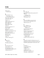
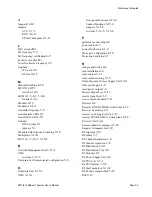
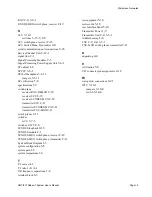
Microwave Networks
RXU
2-2, 3-4-1
RXU-DEMOD switch plane, receiver
2-12
S
SCU
3-12-1
switches
3-12-5, C-5
SCU switch plane, receiver
2-13
SCU Switch Plane, Transmitter
2-11
serial communication port connections
4-16
Service Channel Unit
3-12-1
signal flow
2-1
Signal Processing Modules
2-5
Signal Processing Power Supply Unit
3-6-1
SP cabinet
1-6
SP PSU
3-6-1
SP shelf backplane
3-1-11
jumpers
3-1-11
SP verification
5-8
specifications
1-9
switch plane
receiver RXU-DEMOD
2-12
receiver SCU
2-13
receiver SYNDES-MUX
2-12
transmitter SCU
2-11
transmitter SYNDES-MUX
2-11
transmitter TXU-MOD
2-11
switch planes
2-11
switches
ACU
3-7-3
switches, OWU
C-6
SYNDES loopback
2-16
SYNDES module
2-1
SYNDES-MUX switch plane, receiver
2-12
SYNDES-MUX switch plane, transmitter
2-11
System Block Diagram
1-3
system configuration
5-8
system gain
1-2
system temperature
1-6
T
T/I curves
A-1
T/I ratio
1-8, A-1
T/R frequency separations
1-8
terminal block
6-3
test equipment
5-16
test records
5-18
test, Interface Panel
5-10
Transmitter Power
1-9
Transmitter Unit
2-4, 3-3-1
troubleshooting
6-6
TXU
2-2, 2-4, 3-3-1
TXU-MOD switch planes, transmitter
2-11
U
unpacking
4-4
V
verification
5-8
VF1 connector pin assignments
4-12
W
waveguide, connections
4-21
WTU
3-14-1
jumpers
3-14-4
switch
3-14-4
Summary of Contents for CM7
Page 2: ......
Page 4: ...Page iv 5 04 05 CM7 8 100Base T System User s Manual ...
Page 16: ...Glossary Page xvi CM System Users Manual X Y Z ...
Page 24: ...Microwave Networks CM7 8 100Base T System User s Manual Pagexxiv ...
Page 62: ...Chapter 2 Operation Page 2 18 5 02 05 CM 100Base T System User s Manual ...
Page 64: ...Chapter 3 Module Descriptions Page 3 2 CM7 8 100Base T ...
Page 88: ...Section 3 3 Transmitter Unit Page 3 3 6 CM7 8 System User s Manual ...
Page 96: ...Section 3 5 RF Power Supply Unit Page 3 5 4 CM System User s Manual ...
Page 100: ...Section 3 6 SP Power Supply Unit Page 3 6 4 CM System User s Manual ...
Page 106: ...Section 3 7 Alarm and Control Unit Page 3 7 6 11 18 03 CM 100Base T System User s Manual ...
Page 124: ...Section 3 11 SYNDES Page 3 11 6 CM System User s Manual ...
Page 130: ...Section 3 12 SCU Page 3 12 6 11 18 03 CM 100Base T System User s Manual ...
Page 138: ...Section 3 13 OWU Page 3 13 8 CM System User s Manual ...
Page 150: ...Section 3 15 NMU Page 3 15 6 CM System User s Manual ...
Page 192: ...Chapter 5 Verification Page 5 20 CM System User s Manual ...
Page 194: ...Chapter 6 Maintenance Page 6 2 7 23 03 CM 100Base T System User s Manual ...
Page 224: ...Chapter 6 Maintenance Page 6 32 7 23 03 CM 100Base T System User s Manual ...
Page 226: ...Site Engineering Page 2 CM System User s Manual ...
Page 230: ...Appendix A T I Curves Page A 4 CM7 8 100Base T System User s Manual ...
Page 267: ...Microwave Networks CM System User s Manual PageB 37 ...
Page 268: ...Appendix B QuikLink Page B 38 CM System User s Manual ...
Page 282: ...Appendix D Alarm Codes Page D 6 5 02 05 CM 100Base T System User s Manual ...
Page 290: ...Appendix E Setting Frequency Page E 8 CM7 8 System User s Manual ...
Page 312: ...CM7 8 100Base T System User s Manual Page I 4 Microwave Networks ...


