Chapter 1
General Information
Page 1-2
8/12/03
CM7/8 100Base-T System User’s Manual
Radio Features
The CM7/8 100Base-T radio delivers as much as 101.5 dB of system gain (at 10-3 BER).
A fundamental feature of the CM radio is that the configuration, capacity and protection
scheme, can be upgraded in the field.
Protection schemes include non-protected, redundancy protection, and diversity
protection. Service channels can also be configured for protection. This makes the radio
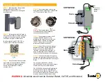
capacities well-suited for a wide range of communication applications. Figure 1-2
illustrates protection switching through the radio.
Other radio features of the design include:
Quadrature Amplitude Modulation
(128-QAM)
modulation scheme that improves spectral perfor-
mance, and meets CTIA requirements for spectral
efficiency.
Forward Error Correction (FEC)
provides error correction for traffic channels and
service channels.
Errorless Space Diversity Switch
hitless receiver switching; may be used as part of a
protection configuration.
Reverse Channel Switching
protects against silent transmitter failures.
Dispersive Fade Margin
radio system is engineered to recover from signal
dispersion.
Adaptive Power Control (APC)
regulates transmitter power output; uses only ade-
quate power for normal operation and increases
output power during a severe fade.
APC also extends the life of the transmitter power
amplifier by reducing power during normal opera-
tion.
Summary of Contents for CM7
Page 2: ......
Page 4: ...Page iv 5 04 05 CM7 8 100Base T System User s Manual ...
Page 16: ...Glossary Page xvi CM System Users Manual X Y Z ...
Page 24: ...Microwave Networks CM7 8 100Base T System User s Manual Pagexxiv ...
Page 62: ...Chapter 2 Operation Page 2 18 5 02 05 CM 100Base T System User s Manual ...
Page 64: ...Chapter 3 Module Descriptions Page 3 2 CM7 8 100Base T ...
Page 88: ...Section 3 3 Transmitter Unit Page 3 3 6 CM7 8 System User s Manual ...
Page 96: ...Section 3 5 RF Power Supply Unit Page 3 5 4 CM System User s Manual ...
Page 100: ...Section 3 6 SP Power Supply Unit Page 3 6 4 CM System User s Manual ...
Page 106: ...Section 3 7 Alarm and Control Unit Page 3 7 6 11 18 03 CM 100Base T System User s Manual ...
Page 124: ...Section 3 11 SYNDES Page 3 11 6 CM System User s Manual ...
Page 130: ...Section 3 12 SCU Page 3 12 6 11 18 03 CM 100Base T System User s Manual ...
Page 138: ...Section 3 13 OWU Page 3 13 8 CM System User s Manual ...
Page 150: ...Section 3 15 NMU Page 3 15 6 CM System User s Manual ...
Page 192: ...Chapter 5 Verification Page 5 20 CM System User s Manual ...
Page 194: ...Chapter 6 Maintenance Page 6 2 7 23 03 CM 100Base T System User s Manual ...
Page 224: ...Chapter 6 Maintenance Page 6 32 7 23 03 CM 100Base T System User s Manual ...
Page 226: ...Site Engineering Page 2 CM System User s Manual ...
Page 230: ...Appendix A T I Curves Page A 4 CM7 8 100Base T System User s Manual ...
Page 267: ...Microwave Networks CM System User s Manual PageB 37 ...
Page 268: ...Appendix B QuikLink Page B 38 CM System User s Manual ...
Page 282: ...Appendix D Alarm Codes Page D 6 5 02 05 CM 100Base T System User s Manual ...
Page 290: ...Appendix E Setting Frequency Page E 8 CM7 8 System User s Manual ...
Page 312: ...CM7 8 100Base T System User s Manual Page I 4 Microwave Networks ...


