Section 3-1
Chassis
Page 3-1-12
CM System User’s Manual
RF Shelf Backplane
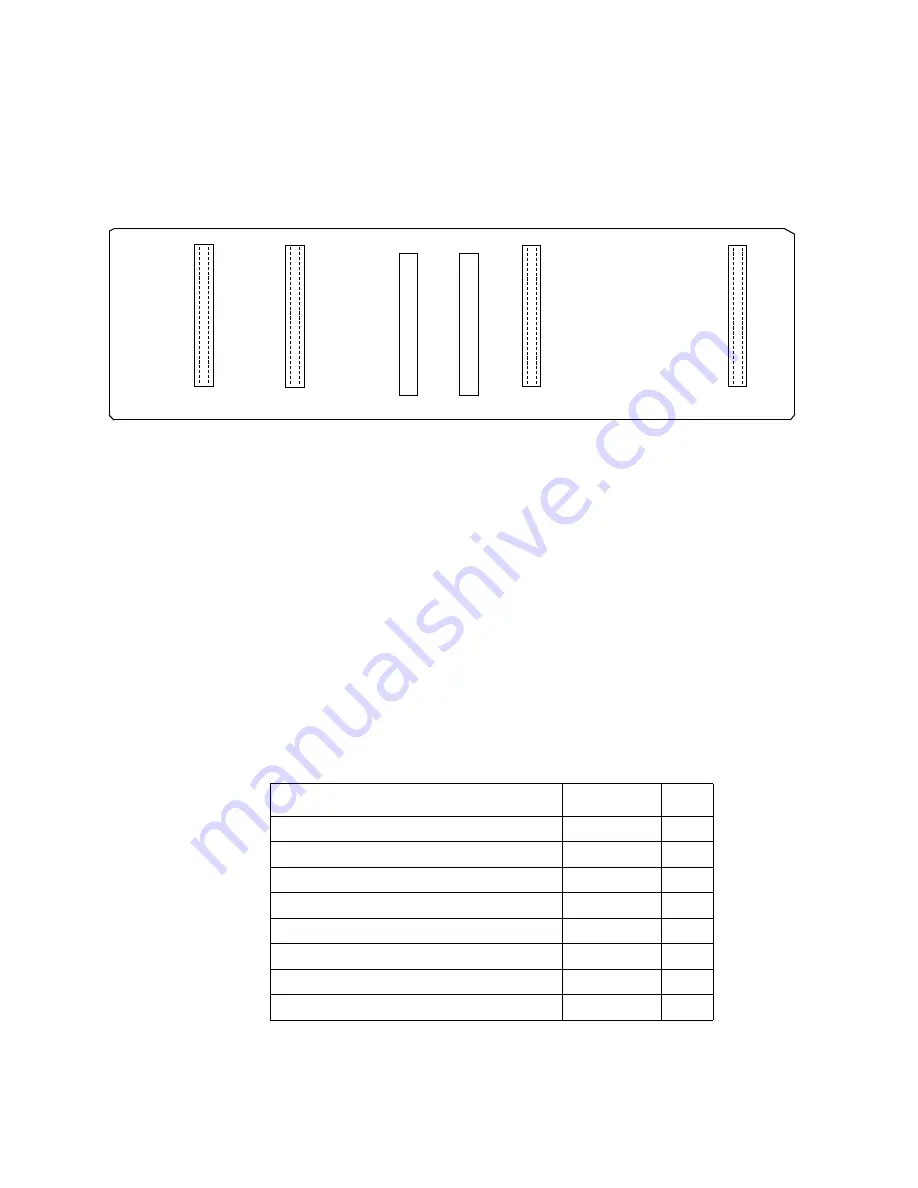
The RF backplane is the interface between the TXU, RXU, RFPSU. Each of these
modules plugs directly into the RF backplane. Figure 3-1-8 illustrates connector
placement on the RF backplane.
Equipment Rack
The standard radio rack accommodates two protected radios. Chapter 4, Installation,
discusses installation and mounting.
Auxiliary Equipment
Install auxiliary equipment two-rack units below the radio cabinet to allow proper cable
routing and sufficient air flow around the radio. For dual-protected radio configurations
space each radio two rack units apart.
When adding a fuse panel, install it one rack unit above the radio cabinet. The fuse panel
is the only auxiliary equipment mounted above a rack.
Installation Accessory Kit
Table 3-1-G lists the contents of the installation kit packed with the radio.
Table 3-1-G. MLN7730 Accessory Kit Contents
ITEM
P/N
QTY
Static Control Wrist Strap
6684760P01
1
Accessory & Installation Tuning Tool
6685389E36
1
1/4 x 5/16 Open End Wrench
6685389E37
1
Cable Assembly–BNC,2 pin HDR, 72", 70MHz
3085465H03
1
Cable Assembly, DS3, PCB-Backplane
3085397H01
2
Fuse, GMT, 120V, Fast Blow, 3 AMP
3110017-09
2
Fuse, GMT, 120V, Fast Blow, 5 AMP
3110017-12
2
Fuse, GMT, 120V, Fast Blow, 10 AMP
3110017-14
2
T
X
U
A
J
6
R
X
U
A
J
5
R
F
P
S
U
A
J
4
J
3
R
X
U
B
J
2
T
X
U
B
J
1
...
...
...
...
...
...
...
...
...
...
...
...
...
...
...
...
...
...
...
...
...
...
...
...
...
...
...
...
F
-1
2
3
8
...
...
...
...
...
...
...
...
...
...
...
...
...
...
...
...
...
...
...
...
...
...
...
...
...
...
...
...
R
F
P
S
U
B
Figure 3-1-8. RF Shelf Backplane
( from the front of the rack)
Summary of Contents for CM7
Page 2: ......
Page 4: ...Page iv 5 04 05 CM7 8 100Base T System User s Manual ...
Page 16: ...Glossary Page xvi CM System Users Manual X Y Z ...
Page 24: ...Microwave Networks CM7 8 100Base T System User s Manual Pagexxiv ...
Page 62: ...Chapter 2 Operation Page 2 18 5 02 05 CM 100Base T System User s Manual ...
Page 64: ...Chapter 3 Module Descriptions Page 3 2 CM7 8 100Base T ...
Page 88: ...Section 3 3 Transmitter Unit Page 3 3 6 CM7 8 System User s Manual ...
Page 96: ...Section 3 5 RF Power Supply Unit Page 3 5 4 CM System User s Manual ...
Page 100: ...Section 3 6 SP Power Supply Unit Page 3 6 4 CM System User s Manual ...
Page 106: ...Section 3 7 Alarm and Control Unit Page 3 7 6 11 18 03 CM 100Base T System User s Manual ...
Page 124: ...Section 3 11 SYNDES Page 3 11 6 CM System User s Manual ...
Page 130: ...Section 3 12 SCU Page 3 12 6 11 18 03 CM 100Base T System User s Manual ...
Page 138: ...Section 3 13 OWU Page 3 13 8 CM System User s Manual ...
Page 150: ...Section 3 15 NMU Page 3 15 6 CM System User s Manual ...
Page 192: ...Chapter 5 Verification Page 5 20 CM System User s Manual ...
Page 194: ...Chapter 6 Maintenance Page 6 2 7 23 03 CM 100Base T System User s Manual ...
Page 224: ...Chapter 6 Maintenance Page 6 32 7 23 03 CM 100Base T System User s Manual ...
Page 226: ...Site Engineering Page 2 CM System User s Manual ...
Page 230: ...Appendix A T I Curves Page A 4 CM7 8 100Base T System User s Manual ...
Page 267: ...Microwave Networks CM System User s Manual PageB 37 ...
Page 268: ...Appendix B QuikLink Page B 38 CM System User s Manual ...
Page 282: ...Appendix D Alarm Codes Page D 6 5 02 05 CM 100Base T System User s Manual ...
Page 290: ...Appendix E Setting Frequency Page E 8 CM7 8 System User s Manual ...
Page 312: ...CM7 8 100Base T System User s Manual Page I 4 Microwave Networks ...


