Section 3-4
Receiver Unit
Page 3-4-2
CM7/8 System User’s Manual
Functional Description
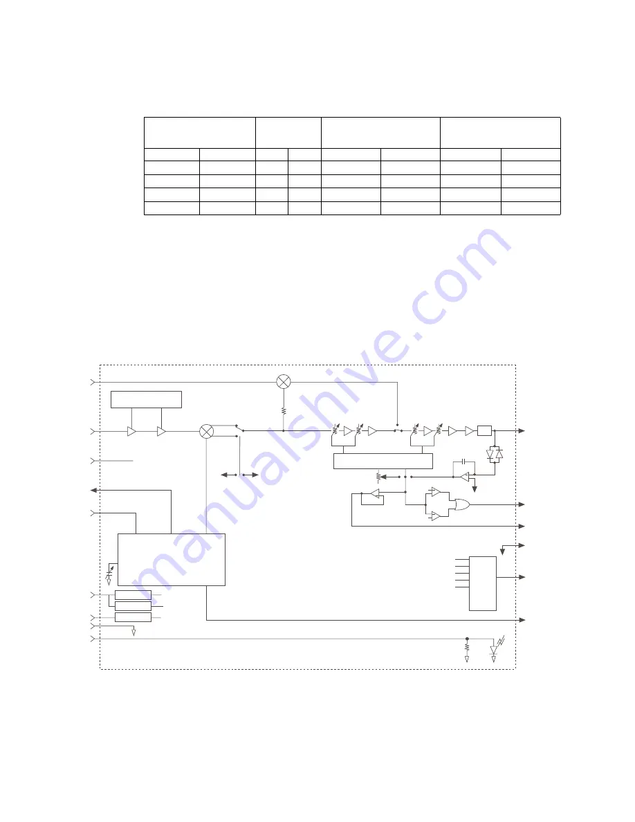
The receiver accepts RF signals from the receive filter and delivers a 70-MHz signal to
the demodulator module (DEMOD). The receiver pre-amplifies and down-converts the
signal using the frequency synthesizer to provide a local oscillator. The receiver amplifies
the resultant 70-MHz signal before sending the signal to the DEMOD.
Figure 3-4-2 is a functional block diagram of the Receiver Unit.
Table 3-4-A. RXU Part Numbers
RXU Part Number
LO Band
Rx LO Frequency (GHz) Synthesizer
Part Number
CM7
CM8
CM7
CM8
CM7
CM8
CM7
CM8
MRL8166A
MRL8170A
7-1
8-1
7.030-7.235
7.850-8.030
MLL8156A
MLL8160A
MRL8167A
MRL8171A
7-2
8-2
7.235-7.440
8.030-8.210
MLL8157A
MLL8161A
MRL8168A
MRL8172A
7-3
8-3
7.440-7.645
8.210-8.390
MLL8158A
MLL8162A
MRL8169A
MRL8173A
7-4
8-4
7.645-7.850
8.390-8.570
MLL8159A
MLL8163A
RF Loopback LO
F-1138
RX Alarm
LO Alarm
MAN
RSL Setpoint 1
RF In
RF
Loopback
Switch
LO MON
+12.3 VDC
-6 VDC
Ground
RX Alarm Control
+11 VDC REG
+5 VDC REG
-5 VDC REG
Linearizer
MUX
2
3
4
Active Bias
AGC Alarm
AGC MON
Ground
Dip Switches
Synthesized
Oscillator
PLL Alarm
LO Output for TXU
RF<LO
RF>LO
LO FREQ SET
LO
FREQ
ADJ
IF OUT
BPF
MUX Out
AGC MON
+
+
+
+
Figure 3-4-2. Receiver Functions
Summary of Contents for CM7
Page 2: ......
Page 4: ...Page iv 5 04 05 CM7 8 100Base T System User s Manual ...
Page 16: ...Glossary Page xvi CM System Users Manual X Y Z ...
Page 24: ...Microwave Networks CM7 8 100Base T System User s Manual Pagexxiv ...
Page 62: ...Chapter 2 Operation Page 2 18 5 02 05 CM 100Base T System User s Manual ...
Page 64: ...Chapter 3 Module Descriptions Page 3 2 CM7 8 100Base T ...
Page 88: ...Section 3 3 Transmitter Unit Page 3 3 6 CM7 8 System User s Manual ...
Page 96: ...Section 3 5 RF Power Supply Unit Page 3 5 4 CM System User s Manual ...
Page 100: ...Section 3 6 SP Power Supply Unit Page 3 6 4 CM System User s Manual ...
Page 106: ...Section 3 7 Alarm and Control Unit Page 3 7 6 11 18 03 CM 100Base T System User s Manual ...
Page 124: ...Section 3 11 SYNDES Page 3 11 6 CM System User s Manual ...
Page 130: ...Section 3 12 SCU Page 3 12 6 11 18 03 CM 100Base T System User s Manual ...
Page 138: ...Section 3 13 OWU Page 3 13 8 CM System User s Manual ...
Page 150: ...Section 3 15 NMU Page 3 15 6 CM System User s Manual ...
Page 192: ...Chapter 5 Verification Page 5 20 CM System User s Manual ...
Page 194: ...Chapter 6 Maintenance Page 6 2 7 23 03 CM 100Base T System User s Manual ...
Page 224: ...Chapter 6 Maintenance Page 6 32 7 23 03 CM 100Base T System User s Manual ...
Page 226: ...Site Engineering Page 2 CM System User s Manual ...
Page 230: ...Appendix A T I Curves Page A 4 CM7 8 100Base T System User s Manual ...
Page 267: ...Microwave Networks CM System User s Manual PageB 37 ...
Page 268: ...Appendix B QuikLink Page B 38 CM System User s Manual ...
Page 282: ...Appendix D Alarm Codes Page D 6 5 02 05 CM 100Base T System User s Manual ...
Page 290: ...Appendix E Setting Frequency Page E 8 CM7 8 System User s Manual ...
Page 312: ...CM7 8 100Base T System User s Manual Page I 4 Microwave Networks ...


