12 |
U s e r ´ s a n d i n s t a l l a t i o n m a n u a l
D R Y S I R E N
P a g e 1 2 o f 6 8
V e r s i o n : 0 1 / 2 0 1 8
SW
IM
M
IN
G
P
O
O
L
D
EH
U
M
ID
IF
IE
R
DR
Y
S
IR
E
N
33 - Cutter – tube
1/2, 3/8
1x
34 - Tube Bender – tube
1/2, 3/8
35 – Saw for iron
1x
6.
INSTALLATION
–
CEILING UNIT
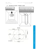
Ceiling unit is designed for an installation at the ceiling or at lower ceiling. Typically the ceiling unit is
fixed into the concreted structure of the upper floor or wooden roof. Please make sure that the
material into which the ceiling unit is to be fixed is suitable for such installation. Manufacturer is not
responsible for damages or losses caused by an incorrect installation or inappropriate concrete or
wood type. Ideally it should be installed above the evaporation source. It should be installed on easy
accessible spot to allow maintenance and service.
Please view following
concrete types and strengths
.
Pressure class
f
ck,cyl
(MPa)
f
ck,cube
(MPa)
Appropriate Threaded
bar TR8 L1
drill depth
Anchor
for
lifting
mechanism
C8/10
8
10
No
N/A
N/A
C12/15
12
15
No
N/A
N/A
C16/20
16
20
Yes
80mm
60mm
C20/25
20
25
Yes
60mm
60mm
C25/30 and more
25 and more 30 and more
Yes
40mm
60mm
Concrete marking with additional request for seepage resistance: STN EN 206-1 –C25/30-XF2,XC2
(SK) – Cl 0,4 – Dmax 16 – S3, seepage 50mm according to STN EN 12390-8.
6.1
BASIC MANIPULATION
The unit is designed to be located on the ceiling. We, at Microwell, had to ensure a perfect balance
between weight and long-term durability with focus on reliability of the product. It is thus necessary
to mind below manipulation information and comply with them. Non-compliance may lead to
product damage, malfunction or failure. Manufacturer is not resosonsible for incorrect manipulation
or for manipulation not compliant to this User’s manual.
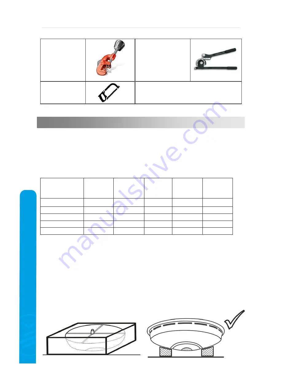
Ceiling unit is delivered in a box with polystyrene support from the bottom at sides.


