24 |
U s e r ´ s a n d i n s t a l l a t i o n m a n u a l
D R Y S I R E N
P a g e 2 4 o f 6 8
V e r s i o n : 0 1 / 2 0 1 8
SW
IM
M
IN
G
P
O
O
L
D
EH
U
M
ID
IF
IE
R
DR
Y
S
IR
E
N
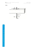
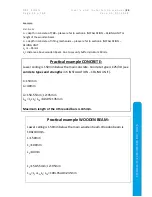
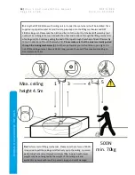
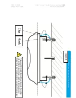
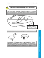
Maximum length of the 4 threaded bars is 235mm.
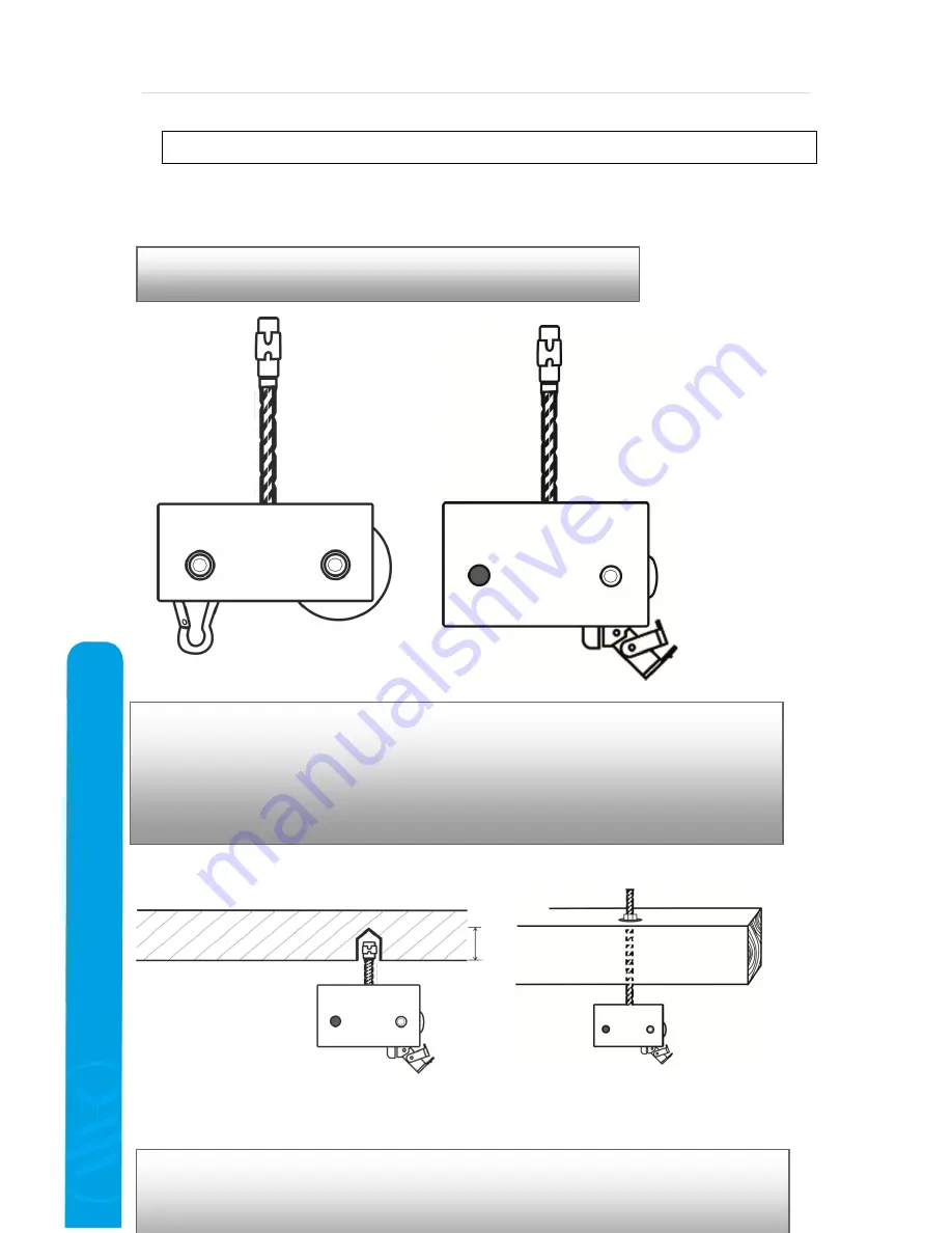
CONCRETE
WOOD
7a
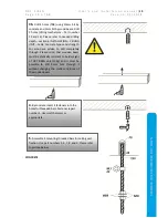
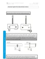
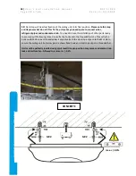
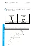
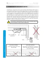
. Lifting mechanism fixation. Please refer to part numbers 13 and 16
Part number 13 (1)
Part number 16 (2)
7b
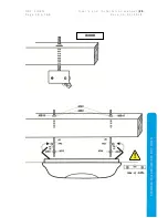
. Please mind the necessary depth in concrete (6 INSTALLATION – CEILING UNIT). Both parts
are equipped with concrete anchors. These must be put inside the hole by force and then the
respective nut inside the part must be tightened until the part is securely fixed into the
concrete. PLEASE NOTE THAT BY WOODEN BEAM WE ADVISE TO FIX THE LIFTING MECHANISM
COMPLETELY THROUGH THE WOODEN BEAM.
7c.
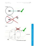
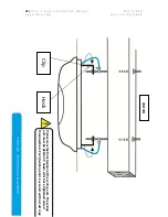
Please mind the direction of part 13 and 16 as a rope will be used to lift the ceiling unit.
Thus the direction of rope should be direct from Back lift assembly (part 13 -1) to Front lift
assembly with locking mechanism (16-2). Please refer to picture below showing view from the


