background image

28 | 

U s e r ´ s   a n d   i n s t a l l a t i o n   m a n u a l  

D R Y   S I R E N  

P a g e   2 8   o f   6 8  


V e r s i o n :   0 1 / 2 0 1 8


SW

IM

M

IN

G

 P

O

O

D

EH

U

M

ID

IF

IE

R


DR

Y

 S

IR

E

N


12.

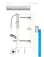
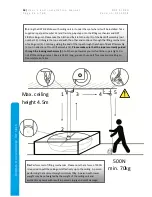
 Next step will be actual fixation of the ceiling unit to its final position. 

Please note this step 

and its process but do not lift or fix the unit yet as you need space to connect wires, 
refrigerant pipes and condensate drain

. You need to have the installation of other parts ready 

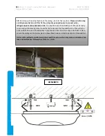
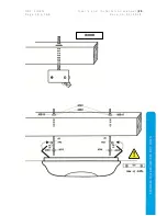
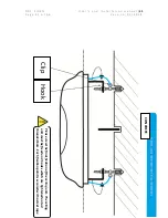
to proceed with following steps. Please fix the hooks onto the threaded bars 4x. Please fix the 
hooks with MX8 on each threaded bar. Secondly attach the steel rope clips onto the ML1 d8 to 
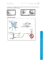
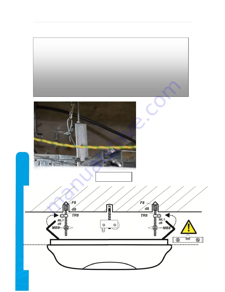
secure the ceiling unit 4x. Below picture shows fixed hook and steel rope clip on a threaded bar. 

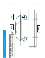
Unit must be perfectly levelled using spirit level! Uneven position may cause condensate drain 
leak and malfunction. Allowed tolerance is +/-0.3%.


MX8 

max. +/-0.3%. 

MX8 

CONCRETE 

Summary of Contents for DRY SIREN due

Page 1: ...SWIMMING POOL DEHUMIDIFIER DRY SIREN SWIMMING POOL DEHUMIDIFIER User s and installation manual Version 01 2018 Model DRY SIREN mono DRY SIREN due ...

Page 2: ...re valid in addition to this User s manual 1 CONTENT 2 2 WASTE DISPOSAL INFORMATION 4 3 SAFETY MEASURES 4 3 1 ELECTRICAL SAFETY 4 3 2 USAGE PRECAUTIONS 5 3 3 HANDLING PRECAUTIONS 6 4 PARTS LIST 7 5 TOOL LIST 10 6 INSTALLATION CEILING UNIT 12 6 1 BASIC MANIPULATION 12 6 2 APPROPRIATE POSITION OF CEILING UNIT 15 6 3 FIXATION ON A CEILING CONCRETE WOOD 17 7 INSTALLATION COMPRESSOR UNIT 33 8 INSTALLAT...
Page 3: ... o n 0 1 2 0 1 8 SWIMMING POOL DEHUMIDIFIER DRY SIREN 14 2 TROUBLESHOOTING SAVE TIME AND MONEY 60 14 3 MAINTENANCE 63 14 4 SUMMER SHUT DOWN 63 14 5 SUPER CHLORINATION CLEANING 63 14 6 START UP DURING CONSTRUCTION 64 14 7 MICROLIGHT 64 15 WARRANTY 64 15 1 INSTALLATION CHECK LIST AND WARRANTY CARD 66 ...

Page 4: ... indoor swimming pool sauna or spa Alternative use is in laundries drying rooms or other humid areas requiring dehumidification Model Microwell DRY SIREN is designed for halls with swimming pool surface of up to 60m2 It is necessary to follow instructions in this User s manual and local regulations in your country that regulate the installation and usage of this device Incorrect improper or operat...

Page 5: ...o intake grilles louvers It could continually overheat the dehumidifier and result in its malfunction or damage Do not climb up on or sit on the unit Do not place any objects on the top of the unit e g boxes flower vases etc Do not hang any objects on the unit Do not spray any flammable substances into the equipment this might lead to fire Do not clean the equipment with aggressive cleaning agents...

Page 6: ...ny improper mechanical force onto the unit This may cause mechanical damage to the device It is forbidden to let the device fall freely onto the ground or any solid surface resulting in hard impact Please notify your reseller or distributor if you suspect that the unit was delivered damaged Unit may seem to work well at start but small damage can make the unit go out of order in short time In such...

Page 7: ...the boxes please check the content It should include the following Name Code Picture Name Code Picture 1 Ceiling unit 1x 2 Compressor unit 1x 3 Tablet with charger 1x 4 User s Manual 1x 5 F8 fastener 4x 6 ML1 D8 fixation double nut 4x 7 MX8 hex nut d8 8x 12x if installation on wooden beam 8 TR8 threaded bar M8x1000mm 2x 9 MB8 flat washer 8x 12x if installation on wooden beam additional washers may...

Page 8: ...chor 1x 17 Wall console for compressor unit 1 set on demand 18 Key set for compressor unit 2x 19 Bluetooth receiver cable only DRY SIREN due The pictures and drawings in Parts list may differ from those actually delivered Some parts may have been delivered upper hand and are thus not included in this shipment If you are unable to locate all parts or are unsure if the supplied parts are complete pl...

Page 9: ...6 10 Lifting mechanism 11 Fixation hooks and Fixation ropes 12 Condensate drain 13 Serial number plate COMPRESSOR UNIT 1 Main cover 2 Door 3 Lock keys 4 Condensate drain 5 Silent blocks 6 Refrigerant connection Suction 1 7 Refrigerant connection Discharge 2 8 Communication cable to ceiling unit 12346 9 Refrigerant plate 10 Serial number plate 11 Main power supply L N Earth 12 Ceiling unit power su...

Page 10: ...UMIDIFIER DRY SIREN 16 Terminal for connection of communication cable 123456 17 Compressor 18 Main PCB 5 TOOL LIST In order to perform the installation correctly you will need following tools Name Code Picture Name Code Picture 19 Drill 1x 20 Drill bit 10mm 1x If installation on a wooden beam 9mm and 11mm drill bit 8 11 12 15 18 16 17 ...

Page 11: ...ips PH2 1x 22 Screwdriver Slot 5 32 1x 23 Small hammer 1x 24 Tape measure 1x 25 Spirit level 1x 26 Combination wrench open end wrench 2x13mm 1x16mm 1x17mm 1x19mm 1x22mm 1x24mm or adjustable multiple 27 Charging and testing hoses with valve 20UNF 2x 28 Vacuum Pump 170l min 1x 29 Charging scales 2g 1x 30 Manifold valve R410A 31 R410A Bottle 1x 32 Flaring tool tube 1 2 3 8 1x ...

Page 12: ...ease view following concrete types and strengths Pressure class fck cyl MPa fck cube MPa Appropriate Threaded bar TR8 L1 drill depth Anchor for lifting mechanism C8 10 8 10 No N A N A C12 15 12 15 No N A N A C16 20 16 20 Yes 80mm 60mm C20 25 20 25 Yes 60mm 60mm C25 30 and more 25 and more 30 and more Yes 40mm 60mm Concrete marking with additional request for seepage resistance STN EN 206 1 C25 30 ...

Page 13: ... such position Do not place ceiling unit on the ground Do not put the unit on an object or support holding the unit in the center Do not place any objects such as drill tools boxes vacuum cleaners etc on the top of the ceiling unit Do not hold ceiling in areas where forbidden bluetooth speaker LED lamp air outlet For manipulation hold the unit on the side which is supported by metal structure Do n...

Page 14: ...G POOL DEHUMIDIFIER DRY SIREN DO NOT INSTALL THE CEILING UNIT IN BETWEEN THE WOODEN BEAMS OR SIMILAR OBJECTS Air flow on the outlet will be reflected from the object wooden beam and redirected back to the unit Thus the water collection process will be dramatically reduced and the unit will be exposed to the risk of overheat ...

Page 15: ...D R Y S I R E N U s e r s a n d i n s t a l l a t i o n m a n u a l 15 P a g e 1 5 o f 6 8 V e r s i o n 0 1 2 0 1 8 SWIMMING POOL DEHUMIDIFIER DRY SIREN 6 2 APPROPRIATE POSITION OF CEILING UNIT ...

Page 16: ...here persons are likely to stay If the unit is in the distance of less or equal to 1250 mm horizontally from the edge of the swimming pool then it must be raised up to the height of 2500 mm from the swimming pool surface if the pool is embedded under the floor then the unit must be raised up to the height of 2500 mm from the floor SWIMMING POOL SWIMMING POOL Swimming pools which are not cleaned by...

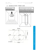
Page 17: ...SWIMMING POOL DEHUMIDIFIER DRY SIREN 6 3 FIXATION ON A CEILING CONCRETE WOOD 1 Locate appropriate location for the ceiling unit 2 Mark the drilling holes according to Scheme diagram Part number 10 Position the drill hole for lifting mechanism 800mm from the center in between the 2 threaded bars TR8 part number 8 800mm ...

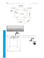
Page 18: ...Y S I R E N P a g e 1 8 o f 6 8 V e r s i o n 0 1 2 0 1 8 SWIMMING POOL DEHUMIDIFIER DRY SIREN 3a Drill 6 holes 4 for TR8 2 for Lifting mechanism We advise to use vacuum cleaner simultaneously when drilling to avoid dust and particles be spread into entire room ...

Page 19: ...CEILING UNIT table Concrete types and strength For wood we advise to drill completely through Please mind that wooden beam must be statically resistant to hold weight of DRY SIREN unit 53kg and it must be possible to drill 9mm hole through it without changing the static conditions of the wooden beam 4 By concrete insert 4 fasteners into the holes for threaded bars Fastener is part number 5 Use sma...

Page 20: ...20 U s e r s a n d i n s t a l l a t i o n m a n u a l D R Y S I R E N P a g e 2 0 o f 6 8 V e r s i o n 0 1 2 0 1 8 SWIMMING POOL DEHUMIDIFIER DRY SIREN WOOD ...

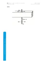
Page 21: ... r s a n d i n s t a l l a t i o n m a n u a l 21 P a g e 2 1 o f 6 8 V e r s i o n 0 1 2 0 1 8 SWIMMING POOL DEHUMIDIFIER DRY SIREN 6 Please refer to picture below in order to fix the final length of threaded bars CONCRETE ...

Page 22: ...22 U s e r s a n d i n s t a l l a t i o n m a n u a l D R Y S I R E N P a g e 2 2 o f 6 8 V e r s i o n 0 1 2 0 1 8 SWIMMING POOL DEHUMIDIFIER DRY SIREN WOOD ...

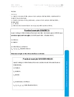
Page 23: ...STALLATION CEILING UNIT L2 L 55mm L3 distance above wooden beam Due to security buffer minimum 40mm Practical example CONCRETE Lower ceiling is 150mm below the main concrete Concrete type is C25 30 see concrete types and strengths in 6 INSTALLATION CEILING UNIT L 150mm L1 40mm L2 150 55mm L2 95mm LTR L1 L2 LTR 40 95 135mm Maximum length of the 4 threaded bars is 135mm Practical example WOODEN BEAM...

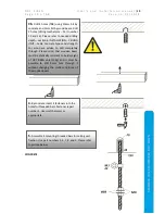
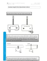
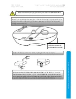
Page 24: ... UNIT Both parts are equipped with concrete anchors These must be put inside the hole by force and then the respective nut inside the part must be tightened until the part is securely fixed into the concrete PLEASE NOTE THAT BY WOODEN BEAM WE ADVISE TO FIX THE LIFTING MECHANISM COMPLETELY THROUGH THE WOODEN BEAM 7c Please mind the direction of part 13 and 16 as a rope will be used to lift the ceil...

Page 25: ...D R Y S I R E N U s e r s a n d i n s t a l l a t i o n m a n u a l 25 P a g e 2 5 o f 6 8 V e r s i o n 0 1 2 0 1 8 SWIMMING POOL DEHUMIDIFIER DRY SIREN CONCRETE WOOD 13 1 16 2 16 2 16 2 13 1 ...

Page 26: ...uiding the end of the rope through the wheel of Back lift assembly 3 out in direction of Front lift assembly 4 Please make sure that the rope is correctly guided through the locking mechanism 5 Pull the rope towards yourself until the rope is tight Do not lift the ceiling unit yet Rope is 14 5m long you can thus use it for a maximum ceiling to floor distance of 4 5m 1 2 3 4 5 9a Perform test of li...

Page 27: ...chanism Please refer to picture below Once you tested the tightness of lifting mechanism and locking mechanism you are ready to proceed to lifting the unit This is designed as one man job 10 Check the final distance of threaded bars and locking hooks on the ceiling unit Should correction be needed untight the hex screws and position to the correct position Tight with hex screw Move right left ...

Page 28: ...s refrigerant pipes and condensate drain You need to have the installation of other parts ready to proceed with following steps Please fix the hooks onto the threaded bars 4x Please fix the hooks with MX8 on each threaded bar Secondly attach the steel rope clips onto the ML1 d8 to secure the ceiling unit 4x Below picture shows fixed hook and steel rope clip on a threaded bar Unit must be perfectly...

Page 29: ...D R Y S I R E N U s e r s a n d i n s t a l l a t i o n m a n u a l 29 P a g e 2 9 o f 6 8 V e r s i o n 0 1 2 0 1 8 SWIMMING POOL DEHUMIDIFIER DRY SIREN max 0 3 WOOD ...

Page 30: ...e 3 0 o f 6 8 V e r s i o n 0 1 2 0 1 8 SWIMMING POOL DEHUMIDIFIER DRY SIREN Clip Hook Please view the final fixation of the ceiling unit The ceiling unit must be fixed on 4 hooks which are tightened onto 4 threaded bars Each fixation point is secured with a steel rope clip WOOD ...

Page 31: ...3 1 o f 6 8 V e r s i o n 0 1 2 0 1 8 SWIMMING POOL DEHUMIDIFIER DRY SIREN Hook Clip Please view the final fixation of the ceiling unit The ceiling unit must be fixed on 4 hooks which are tightened onto 4 threaded bars Each fixation point is secured with a steel rope clip CONCRETE ...

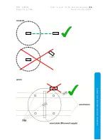
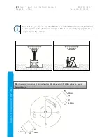
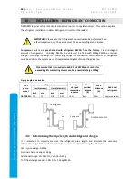
Page 32: ...IREN 13 It is advised to construct 2 service hatches 400x400 next to DRY SIREN ceiling unit as per below drawing When installing you may use help of scaffold base or ladder Mind all local work health and safety requirements Manufacturer is not responsible for injuries caused by inappropriate tools equipment or work procedures 400mm 400mm 400mm 400mm ...

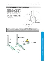
Page 33: ... silent blocks ideally to be installed on a wall console This part describes the fixation on a wall console Please refer to position of the compressor unit in terms of surrounding walls and objects 1 Locate the appropriate location for compressor unit Drill 4 holes for fixation screws and fix the wall consoles on a wall Make sure the wall console is leveled with spirit level with max deviation of ...

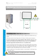
Page 34: ...ly cable 2 5mm2 CYSY three core Live Neutral Earth The main circuit breaker switch of the compressor unit must be situated outside of the swimming pool hall The main switch of the unit must be bipolar with switch out breaking of conductors L and N An appliance for disconnecting the unit from the mains must be embedded into a firm surface The distance of contacts when switched off must be at least ...

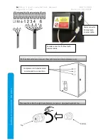
Page 35: ... markings L1 N1 Earth Both cables are to be connected to both ceiling and compressor unit Ceiling unit electrical and communication connection 2 Open the black connection box with hand pushing from the sides and pull up 3 Please connect all connections with respective markings L1 N1 Earth 1 2 3 4 6 for DRY SIREN mono and L1 N1 Earth 1 2 3 4 6 for DRY SIREN due The connections 5 and 7 are for Bluet...

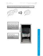
Page 36: ...L DEHUMIDIFIER DRY SIREN 4 Take both cables and connect them onto terminals into compressor unit Compressor unit electrical and communication connection 5a Lead the cables through the cable joint connectors Unscrew the plastic top Top Bottom Female connector for bluetooth receiver cable Male connector for bluetooth receiver cable ...

Page 37: ...FIER DRY SIREN 5b Lead the cable through the top to bottom Then tighten the top back 6 Please connect the ceiling unit power supply cable L1 N1 Earth and compressor unit main power supply cable L N Earth onto the compressor terminal connection 7 Please connect the communication cable 1 2 3 4 6 for DRY SIREN mono 1 2 3 4 6 for DRY SIREN due ...

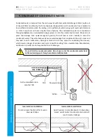
Page 38: ...e the drainage hose upwards against gravity this will lead in unit s inability to drain the condensate water This will subsequently cause water leakage from underneath the unit s cover and may lead to unit s malfunction damage or failure Also it may cause the underlying floor be wet which creates danger of accident and harm to health resulting from unwanted slip Manufacturer distributor or reselle...

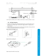
Page 39: ...HUMIDIFIER DRY SIREN Compressor unit is supplied with a condensate drain hose Please follow instructions below to correctly install the condensate drainage Correct drain hose Incorrect drain hose installation CONDENSATE DISCHARGE Condensate drain Condensate drain Condensate drain Condensate drain tub Bath tub basin plumbing Overflow ...

Page 40: ...erant connection Certain amount of refrigerant must be added to the system per each meter exceeding 8m of connecting distance Please note that it is needed to add 30g of R410A per 1 meter for exceeding 8m connecting distances above nominal charge 1 05kg Piping length and elevation Heat pump model Pipe size Factory pre charged connection distance Max vertical distance B Max distance A Additional re...

Page 41: ...ign the center of the pipes and sufficiently tighten the flare nut by hand Please do so for both Suction and Discharge pipes Suction pipe has bigger diameter Discharge pipe has smaller diameter II Tighten the flare nuts with torque wrench until the wrench clicks Please make sure that the direction for tightening follows the arrow on the wrench Pipe connection on compressor unit Pipe connection on ...

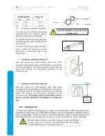
Page 42: ... 2 Compressor unit above ceiling unit Tape the piping and interconnecting cable from down upwards Fix the tapped piping with cable binder or equivalent onto the exterior wall It is important to make a trap to prevent water from entering into the electro installation of the compressor unit On refrigerant side it is important to form a syphon to avoid compressor s oil leakage into ceiling unit coils...

Page 43: ...ressure in the system rises 2 Operating current rises 3 Dehumidification efficiency drops 4 Blockage of Electronic expansion valve due to frozen moisture resulting in complete failure of the unit 5 Corrosion of refrigerant circuit It is thus highly advised to take a leak test after evacuating the complete system Leak test can be performed with usual methods using manifold valve and or soap water A...

Page 44: ... Tube length less than 10m Tube length more than 10m Minimum 20 minutes Minimum 30 minutes c When the desired vacuum is reached close the Lo knob of the manifold valve and stop the vacuum pump d Close the valve on charging hose at vacuum pump 3 Refrigerant filling a Now remove the vacuum pump and bring the refrigerant bottle and charging scales Connect the disconnected hose point d above to refrig...

Page 45: ...e DO NOT RUN THE UNIT WITHOUT REQUIRED AMOUNT OF REFRIGERANT j When the required amount of refrigerant has been filled into the system first close the valve at suction at compressor unit and remove the valve from compressor unit Please make sure you close the valve on bottle and Lo knob on manifold valve k Put service valve caps back at both suction and discharge side service valves and fasten the...

Page 46: ... information DRY SIREN s pairing is protected by double password entry This is to avoid third parties logging into your DRY SIREN device DRY SIREN licence plate is located on the inside of the compressor unit s door The plate looks like following DRY SIREN LICENCE EXAMPLE SN XXXXXXXX SN 17164001 Real ID YYYYYYYY Real ID 9LheRL6q PASSWORD PASSWORD 123456789 APP LOGIN XXXXXXXX APP LOGIN 17164001 APP...

Page 47: ...UMIDIFIER DRY SIREN 2 Turn the supplied tablet on via pressing and holding upper right button on the side Supplied tablet type may be Acer Iconia One 7 or similar Please wait until tablet starts and goes to home screen 3 Connect the tablet to your WIFI Go to Wi Fi Select your WIFI hotspot network in our case MicrowellAP Go to settings ...

Page 48: ...g e 4 8 o f 6 8 V e r s i o n 0 1 2 0 1 8 SWIMMING POOL DEHUMIDIFIER DRY SIREN 4 Open the Microwell application on home screen Wait until you enter the application If necessary insert network password and press connect After you are successfully connected proceed to next step ...

Page 49: ...sary to activate DRY SIREN access point This is activated by pressing and holding the PAIR button on compressor unit for 3 seconds White colored LED light flashing on ceiling unit will signalize that the unit is ready to pair You will also notice increased performance of the fan on the ceiling unit Wait until the application starts then press PAIR AGAIN At this moment please Confirm by pressing PA...

Page 50: ...DRY SIREN 9LheRL6q Press FIND DRY SIREN Press FIND HOME WIFI WIFI hotspot in our case MicrowellAP Press CONNECT If the device requires password insert password 9 digit password from Licence plate Please mind that 0 is zero key and 3 is number 3 key Then press CONNECT Once it shows Connected you have to jump back with Back screen button to proceed to the next screen Once it shows Connected you have...

Page 51: ...Y SIREN 9 Wait for password window and insert password 10 Step 3 5 Press SELECT DRY SIREN Press CONNECT Then press CONNECT Select DRY SIREN 9LheRL6q Once it shows Connected you have to jump back with Back screen button to proceed to the next screen Once it shows Connected you have to jump back with Back screen button to proceed to the next screen ...

Page 52: ... 11 Step 4 5 12 If there is working internet connection correct password and all working properly your set up is complete Select your internet connection WIFI hotspot in our case MicrowellAP Press CONNECT Press SELECT HOME WIFI Press START USING DRY SIREN Once it shows Connected you have to jump back with Back screen button to proceed to the next screen ...

Page 53: ... run it for testing When the unit is given command to dehumidify required humidity below actual in order to protect the compressor the units starts to collect water after 3minutes Minimum water collection time compressor on is 5 minutes Please turn to next section for more information about application description and control DRY SIREN remembers the pairing If there is a power supply cut or you tu...

Page 54: ...over WIFI and mobile application allows the user to take over full control of the unit dehumidification process LED lamp microLIGHT and Bluetooth speaker Do not run the unit without required amount of refrigerant Before you proceed make sure that all installation electrical refrigerant etc According to this user s manual had been done correctly and in full compliance to this user s manual Descript...

Page 55: ...1 8 SWIMMING POOL DEHUMIDIFIER DRY SIREN Humidity control Humidity settings You can set any from 1 to 99 The system will advise you when set under 40 or above 70 Back to Home screen button Current humidity microLIGHT indication of current humidity Status of the DRY SIREN microLIGHT indication of requested humidity ...

Page 56: ...r s i o n 0 1 2 0 1 8 SWIMMING POOL DEHUMIDIFIER DRY SIREN Lamp control Back to Home screen button LED lamp ON OFF LED lamp manual brightness disabled when auto brightness is on LED lamp Auto brightness ON OFF LED lamp color temperature microLIGHT ON OFF microLIGHT indication of current humidity ...

Page 57: ...me screen and turn the Music player on Music can be played from any source streaming like youtube Spotify memory card etc Turn the speaker on To activate the speaker go to Tablet s Bluetooth settings and turn the Bluetooth on Device will find and pair itself with DRY SIREN speaker Bluetooth speaker ID e g JPM2021 By DRY SIREN due please mind MASTER and SLAVE units Master unit is visible for Blueto...

Page 58: ...ight x depth mm 1400 x 1550 x 850 Weight kg Ceiling 53 Condensing 20 Amount of refrigerant R 410 A kg minimum 1 05kg 2 088t CO2 ekv 1 0kg R410A Max pressures in the system HP LP bar 28 5 8 5 WIFI specification Standard worldwide IEEE802 11b g n 2 412 2 484 GHz Internet connection minimum 40kB s 13GB per month data volume Bluetooth speaker 80W stereo 80Hz 20kHz 4 8Ω Bluetooth 3 0 EDR LED lamp 50W W...

Page 59: ... i o n 0 1 2 0 1 8 SWIMMING POOL DEHUMIDIFIER DRY SIREN 13 2 Extraction rate diagram 13 3 Wiring diagram CEILING UNIT SIREN TO COMPRESSOR UNIT L1 N1 1 2 3 4 6 COMPRESSOR UNIT POWER SUPPLY POWER SUPPLY UNIT COMMUNICATION 230VAC TO CEILING L N L1 N1 1 2 3 4 6 FUSE RS232 PAIR SWITCH R BR BL CM 5 16A C ...

Page 60: ...or internet connection in general Please turn to section 14 2 Troubleshooting save time and money for more information how to resolve this error ERROR IN SENDING COMMAND User will be notified by a short pop up message in the application if the requested command experienced error in processing Normally when a command is successfully processed a short pop up message appears SENDING COMMAND Typically...

Page 61: ...ion Once you see this error please wait 5 10 seconds Sometimes when response from server due to internet connection is slower temporarily max 10seconds the DRY SIREN may be UNREACHABLE 1 Check your WIFI network is working and that is it connected to the internet Sometimes your WIFI network signals properly but your WIFI router does not have internet access This may the case of malfunction of your ...

Page 62: ...is normal that DRY SIREN does not operate because it has reached requested humidity level If you feel that the air is humid or you have condensation decrease the requested level of humidity DRY SIREN does not work for 3 minutes and then it starts This is normal It is time protection for compressor DRY SIREN operates too short Please allow DRY SIREN to run 24 hours and then check the humidity again...

Page 63: ...s the job of humidity control for few weeks of the year Although following rapid change in weather e g into rainy days may result in high humidity in your pool In this case please make sure that 1 Dehumidifier s circuit breaker is off i e dehumidifier does not have any power supply 2 Dehumidifier is cleaned of dust fluff or other dirt that may harden stiffen its structure during the shutdown perio...

Page 64: ...ty OK you have green light When you uncover it and start swimming it is possible that after some time the microLIGHT will turn to some gradient of yellow orange or red This signalizes that your humidity is rising Do not be disturbed this is normal Once you stop using the pool for the day and cover it DRY SIREN should dry the air out in maximum few hours depending on actual sizing of your pool and ...

Page 65: ...ximum copper content ppm max 2 Aquamatic single purifier ppm max 2 Tarn clean purifier ppm max 2 Sherwood purifier ppm max 2 Table Allowed chemical conditions TRANSPORT INSTRUCTIONS When applying for warranty please contact your distributor and indicate dehumidifier model and serial number Please describe the genesis of the failure The compressor unit must be transported in the original packaging ...

Page 66: ...correctly max 20cm upward then declivity no waving no elevation end by siphon YES NO Electrical connection done OK YES NO Refrigerant connection done OK YES NO Leak test performed without leakage s detected YES NO System vacuuming performed YES NO Connecting refrigerant distance meters Final refrigerant charge kg R410A Mobile application successfully paired and tested YES NO Bluetooth speaker succ...

Page 67: ...D R Y S I R E N U s e r s a n d i n s t a l l a t i o n m a n u a l 67 P a g e 6 7 o f 6 8 V e r s i o n 0 1 2 0 1 8 SWIMMING POOL DEHUMIDIFIER DRY SIREN NOTES ...

Page 68: ...EHUMIDIFIER DRY SIREN Manufacturer MICROWELL spol s r o SNP 2018 42 927 01 Šaľa Slovakia tel 421 31 702 0540 fax 421 31 702 0542 e mail microwell microwell sk w w w m i c r o w e l l e u M a d e i n E U Distributed by ...

Reviews: