27
DL451 Modular I/O
Operator Manual
Chapter 3: Front Panel
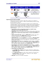
The front panel comprises various sections, as follows:
Control panel
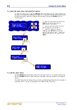
The control panel is used for setting up the DL451 Modular I/O unit via a main menu. It
comprises an LCD panel and four buttons. The LCD panel also displays unit information
during operation. Each button illuminates with a blue backlight when pressed.
3
6
7
2
4
5
1
1
Ventilation panels.
Do not obstruct.
2
psu
power supply unit monitoring panel;
see page 28.
3
Ethernet control
panel; see page 28.
4
AES50 audio
panel monitors; see
page 28.
5
Control panel containing LCD display and
four pushbuttons; see page 27.
6
Three rows of eight write-on strips for
manually marking the
A
,
B
or
C
module
analogue/digital channel assignments.
7
Cut-outs for rack mounting fixings.
4
1
4
3
2
1
LCD display
comprising 32 characters
(2x 16). Shows default screen during normal
operation and is used conjunction with the four
adjacent buttons to program the DL451
Modular I/O from the main menu.
2
SELECT
button for selecting the option
currently displayed.
3
Navigation
MENU
button for entering
menu mode, as shown on the LCD display.
Button illuminates with a blue backlight when
pressed.
4
Up and down navigation buttons for
scrolling up and down through the main menu
options.
Summary of Contents for DL451
Page 2: ......
Page 4: ......
Page 6: ......
Page 16: ...xvi DL451 Modular I O Operator Manual...
Page 20: ...4 Chapter 1 Introduction DL451 Modular I O Operator Manual...
Page 42: ...26 Chapter 2 XL8 Live Performance System Overview DL451 Modular I O Operator Manual...
Page 50: ...34 Chapter 4 Rear Panel DL451 Modular I O Operator Manual...
Page 72: ...56 Appendix A Functional Block Diagram DL451 Modular I O Operator Manual...

