Check for possibility of reverse draft which can be caused by wind deflecting from an
obstruction in the proximity of the chimney exit or by exhaust fans in the building.
A continuous draft is required for the proper operation of the pilot. This is no problem in the
usual up-draft gas utilization equipment. However, in down-draft or horizontal gas utilization
equipment, especially during periods of infrequent operation, the available draft may become
nil and result in persistent pilot outages. ECONOMITE Model DS45B with direct spark ignited
main flame is recommended for those applications.
Maximum acceptable draft: minus 0.2" W.C.
Note: BEFORE SERVICING
, mark with a scribe line or measure opening of primary air shutter
so that it can be reset to its original position following servicing.
Cleaning of the blower wheel is usually the only service required. Need for cleaning is indi-
cated if the air cage assembly shows an accumulation of dust and lint, or if the character of the
flame indicates a deficiency of air. Motor cooling air vents, if present, should also be cleaned at
this time.
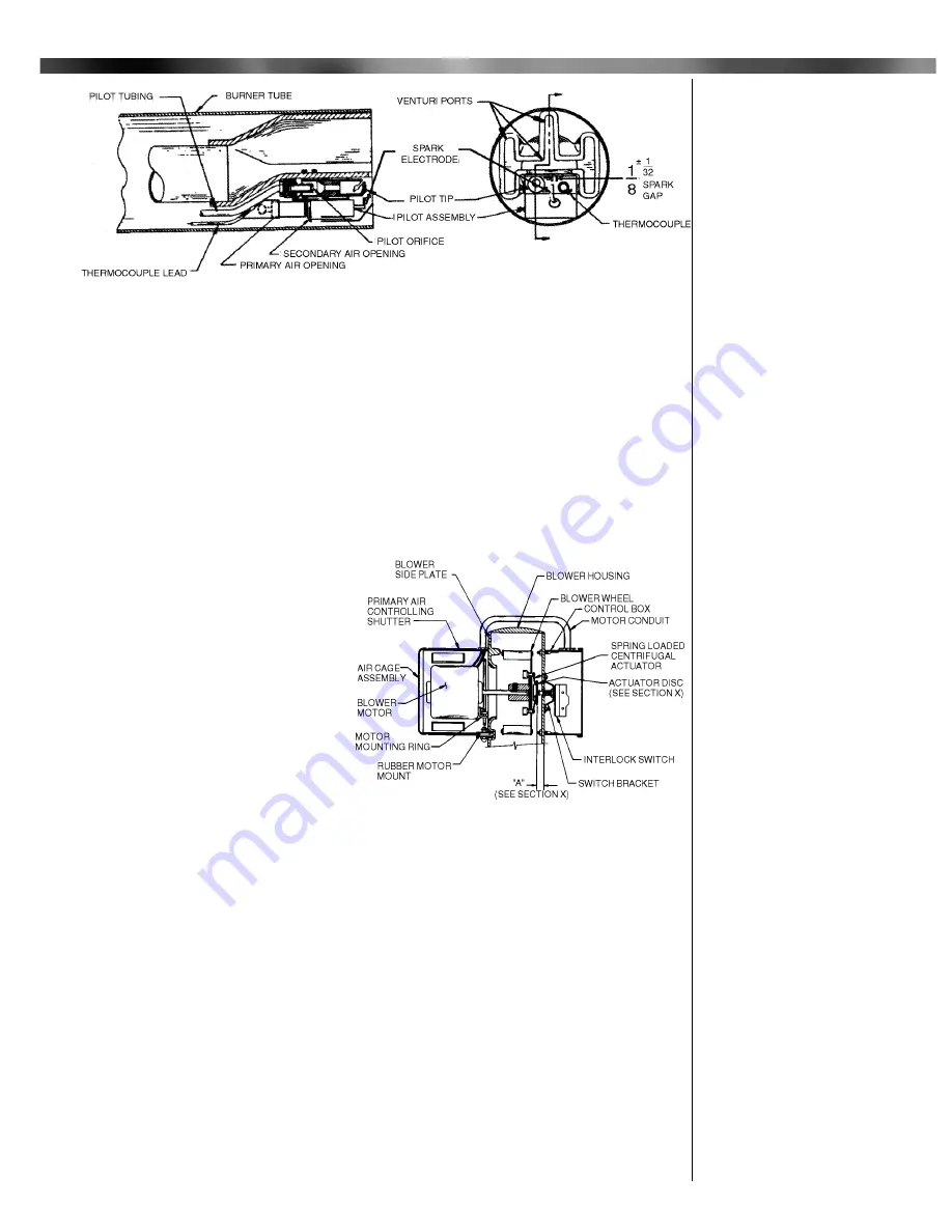
The Blower side Plate, Motor and
Wheel are removed as an assembly.
Disconnect the motor wires from Burner
Terminal
2
and Motor Relay
4
. Disconnect
the Motor Conduit from the Control Box
and remove the Side Plate screws.
The Blower Wheel is equipped with a
spring loaded centrifugal actuator to oper-
ate and electrical interlock switch, so as
to prevent the burner from firing if the
Blower Wheel is not running at its operat-
ing speed. When the motor is off, the
actuator spring forces the disk against the
switch plunger to push it past its operating
point. When running, the actuator pulls
the disk clear of the plunger.
To make a specific test of the interlock circuit:
1.
Turn burner power OFF.
2.
Turn Manual Gas Cock Knob on Combination Valve to OFF.
3.
Disconnect the motor wire from Terminal
4
of the motor relay to keep the motor off.
4.
Turn burner power
ON
and set the operating control to
ON
or thermostat to call for heat.
Check for 24V between the Combination Valve Terminals.
A.
No voltage: Interlock Circuit OK.
B.
Voltage present: check that switch bracket is screwed down tight (See Figure 9). If so,
without disconnecting switch wires, remove switch bracket and manually depress
switch plunger. If voltage is still present, or if the plunger has to be depressed to
where dimension
A
of Figure 9 is less than
9
/
32
" when switch clicks over, replace the
switch.
5.
If the switch tests OK, check dimension A of Figure 9 as follows:
Switch plunger free…………
9
/
32
"to
11
/
32
"
Disk free………………..…
7
/
32
to
1
/
4
"
Disk held all the way in….
15
/
32
" min.
6.
If plunger dimension is wrong, replace switch. If disk dimension is wrong, check that the
actuator operates freely with a minimum movement of
1
/
4
" from the free position. If movement
is OK, reposition blower wheel on motor shaft, if not replace wheel.
IX Venturi Casting
and Pilot Continue
d
9
Figure 8: Venturi Casting and Pilot Assembly
Figure 9: Blower Assembly
X Blower Assembly


