background image

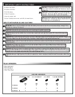
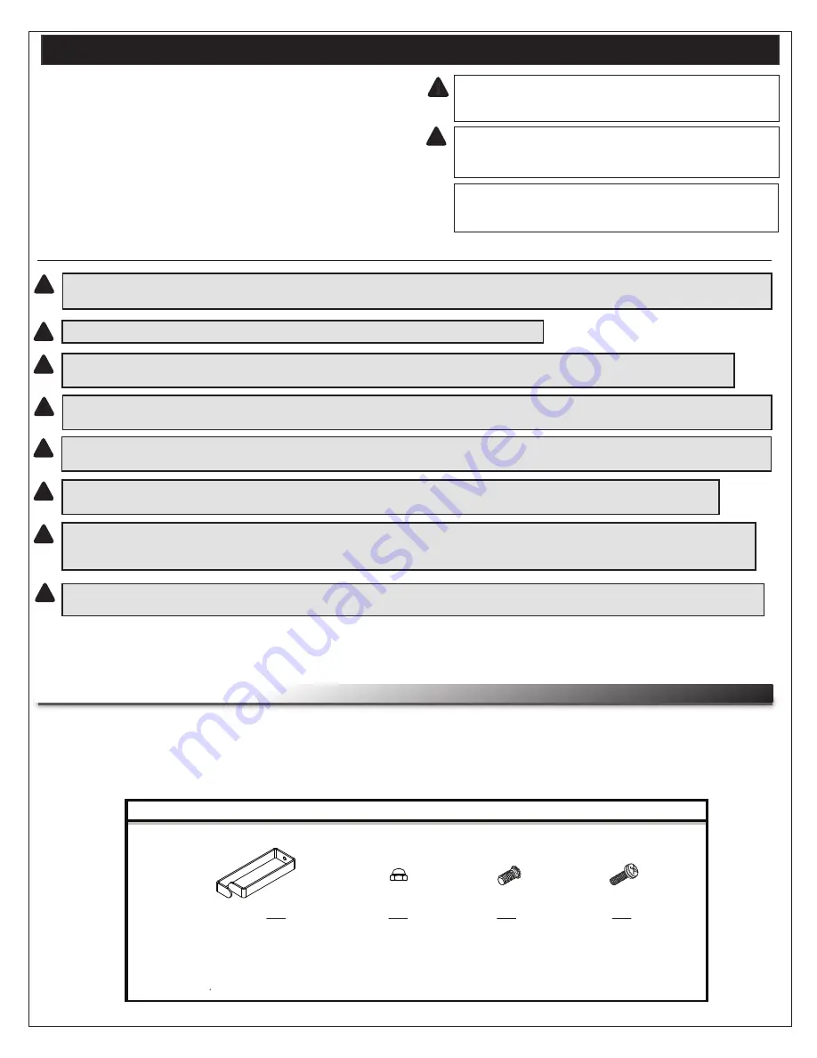
STANDARD D-RING

8-32 ACORN NUT

8-32 STUD     

QTY

QTY

QTY                                     QTY

 12 SPACE 

4

4

4                                50                                       

 18 SPACE 

6

6

6                                50

 26 SPACE

8

8

8                                50

SUPPLIED HARDWARE

12-24 RACKSCREW

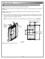
IMPORTANT SAFETY INSTRUCTIONS 

WARNING:

 A WARNING ALERTS YOU TO A SITUATION

THAT COULD RESULT IN SERIOUS PERSONAL INJURY

OR DEATH. 

!

!

IMPORTANT WARNINGS AND CAUTIONS!

WARNING! 

Failure to read, understand and follow the following information can result in serious personal injury, damage to the

equipment or voiding of the warranty.

NOTE:

 A NOTE IS USED TO HIGHLIGHT PROCEDURES

PERTAINING TO THE INSTALLATION, OPERATION OR

MAINTENANCE OF THE PRODUCT.

CAUTION: 

A CAUTION ALERTS YOU TO A SITUATION

THAT MAY RESULT IN MINOR PERSONAL INJURY OR

DAMAGE TO THE PRODUCT AND / OR PROPERTY.

• Read these instructions

.

• Keep these instructions.

• Heed all warnings.

• Follow all instructions.

• Clean only with dry cloth.

• Only use attachments/accessories specified by the manufacturer.

CAUTION: 

All installation and assembly steps must be performed by qualified personnel.

CAUTION: 

Ensure that the wall/floor has a structural load capacity that will support the weight of the cabinet fully loaded with

equipment. 

CAUTION: 

Some parts of the enclosure system may not be effectively bonded to the Protective Earth Terminal (PET). If these parts

need to be bonded to the PET it should be done in accordance with Article 250 of the National Electrical Code. 

CAUTION: 

Power cord(s), for fans or other accessories, need to be secured to ensure that they are routed away from pinch points

and moving parts.

CAUTION: 

Do not attempt to unload or move the enclosures alone. Make sure to have sufficient amount of personnel and

equipment to safely move this product.

CAUTION: 

The following parts are not effectively bonded to the protective earth terminal: Rackrails, lace bars, Lever Lock™,

shelving, baffles, blank panels, and cable management equipment. If any part needs to be bonded to the protective earth terminal

it shall be done in accordance with Article 250 of the National Electrical Code.

!

!

!

!

!

!

!

!

• 5/16” Wrench

• 5/16” Socket

• 5/32” Hex Key

TOOLS REQUIRED

CAUTION: 

Maximum weight capacity is 200 lbs. 

As a general rule, heavier equipment should be placed towards the bottom of the

rack.

!

Summary of Contents for Cablesafe CWR Series

Page 1: ...bling this product PRODUCT FEATURES 26 width provides abundant space for patching Ships with front rackrail at a 4 setback to accomodate cable managers Swing open center section allows for easy front and rear access to equipment and cabling Available with vented plexiglass or solid doors CABLESAFE WALL CABINET WITH 4 DEEP DOOR CABLESAFE WALL CABINET WITH STANDARD DOOR UL R C US LISTED I 00347 Rev ...

Page 2: ...l CAUTION Ensure that the wall floor has a structural load capacity that will support the weight of the cabinet fully loaded with equipment CAUTION Some parts of the enclosure system may not be effectively bonded to the Protective Earth Terminal PET If these parts need to be bonded to the PET it should be done in accordance with Article 250 of the National Electrical Code CAUTION Power cord s for ...

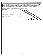
Page 3: ...of two 2 3 4 plywood screwed to the studs 2 Locate the studs in the wall behind the two 2 plywood Align the mounting holes in the cabinet with the studs Using 3 8 diameter lag bolts with a minimum length of 2 and flat washers in each mounting hole secure the cabinet to the wall NOTE A minimum of 1 clearance on the top and bottom of the cabinet is required FIGURE A 1 Separate backpan from center se...

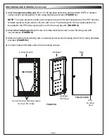
Page 4: ...onnection to the backpan PET Protective earth and bonding connections shall be in accordance with Article 250 of the National Electric Code OPTIONAL PROTECTIVE EARTH TERMINAL KIT PET K CWR PARTS LIST Backpan bonding wire 12 Gauge Wire 10 ring terminal to 1 4 ring terminal 9 Door bonding wire 12 Gauge Wire 10 ring terminal to 10 ring terminal 9 Thread forming screw M4 x 7 Locking Nut 10 32 Flange N...

Page 5: ...minal placed on the PET and this terminal needs to be secured on its own with a nut The bonding wire for the center section can be added to the PET after securing the nut for the main ground FIGURE G 2 Attach door bonding wire with male or female disconnect end to door bonding stud with nut included FIGURE G 3 Attach remaining door bonding wire to nearest center section bonding stud 10 32 using ha...

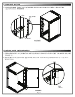
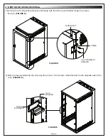
Page 6: ...ardware FIGURE B 2 Reverse the door to install to the opposite side of the rack Install the two 2 10 32 screws to the top and bottom hinges D RING RACKRAIL 8 32 ACORN NUT FIGURE B 8 32 STUD 1 Remove the two 2 10 32 screws from both top and bottom hinges to remove the door remove 4 screws total FIGURE C D RING INSTALLATION STANDARD DOOR SWING REVERSAL ...

Page 7: ...removing the 2 two 10 32 screws Install the latch to the opposite side of the rack FIGURE E 1 Remove the 1 4 20 panhead screws and flange nuts from the top and bottom hinges to remove the door FIGURE D HINGE 1 4 20 PANHEAD SCREWS FIGURE D FLANGE NUT 4 DEEP DOOR SWING REVERSAL ...

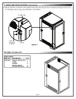
Page 8: ...ead screws and 2 two 1 4 20 flange nuts per hinge top and bottom FIGURE F PART NO DESCRIPTION QTY CWR FKIT FANS 95 CFM per fan 2 CORDS 2 GUARDS 2 VENT BLOCKER 1 NYLON PUSH RIVET 20 CWR FAN KIT HINGE 1 4 20 PANHEAD SCREWS FLANGE NUT 4 DEEP DOOR SWING REVERSAL Continued FIGURE F OPTIONAL COOLING KIT ...

Page 9: ... ANY KIND EITHER EXPRESSED OR IMPLIED INCLUDING BUT NOT LIMITED TO IMPLIED WARRANTIES OF MERCHANTABILITY AND FITNESS FOR A PARTICULAR PURPOSE TO THE MAXIMUM EXTENT PERMITTED BY APPLICABLE LAW IN NO EVENT SHALL THE COMPANY BE LIABLE FOR ANY SPECIAL INCIDENTAL INDIRECT OR CONSEQUENTIAL DAMAGES WHATSOEVER INCLUDING WITHOUT LIMITATION DAMAGES FOR LOSS OF BUSINESS PROFITS BUSINESS INTERRUPTION OR ANY O...

Reviews: