background image

Page 6 

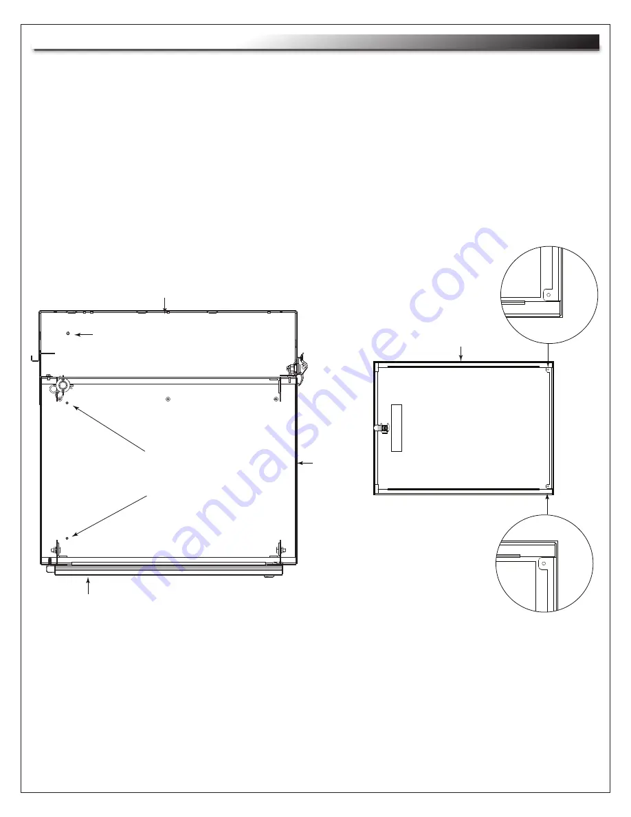
GROUNDING AND BONDING

Center

Section

Backpan

Door

Center Section Bonding Studs

10-32 (2 Upper and 2 Lower) 

Backpan PET Stud

Door Bonding Points

(1 Upper and 1 Lower)

1) Attach 

backpan bonding wire

 from 1/4”-20 backpan protective earth terminal (PET) to nearest

  center section bonding stud (10-32) using hardware provided. 

(FIGURE G) 

 NOTE:

 The main protective earth ground needs to be the first terminal placed on the PET and this

  terminal needs to be secured on its own with a nut. The bonding wire for the center section can

  be added to the PET after securing the nut for the main ground. 

(FIGURE G) 

2) 

FOR OPTIONAL DOOR: 

Attach 

door bonding wire

 (with male or female disconnect end) to door

  bonding point with self-tapping screw (included). 

(FIGURE G) 

3) Attach remaining door bonding wire to nearestcenter section bonding stud (10-32) using hardware

 provided. 

(FIGURE G) 

4) Connect male and female ends of door bonding wire set.

FIGURE G

OVERHEAD VIEW

FRONT VIEW

Door

Summary of Contents for EWR Series

Page 1: ...structions thoroughly before installing assembling this product PRODUCT FEATURES Ideal for both secure and non secure areas Tool free Quick Mount system for easy one person mounting of the center section to the backpan Vented center section enables the effective passive thermal management UL R C US LISTED TM I 00076 Rev H ...

Page 2: ...ed all warnings Follow all instructions Clean only with dry cloth Only use attachments accessories specified by the manufacturer Page 2 CAUTION All installation and assembly steps must be performed by qualified personnel CAUTION Ensure that the wall floor has a structural load capacity that will support the weight of the cabinet fully loaded with equipment CAUTION Some parts of the enclosure syste...

Page 3: ...ired 5 Using 3 8 toggle bolts and standard flat washers mount backpan to plywood FIGURE C NOTE Unit must be installed plumb and level NOTE All mounting holes must be used NOTE The mounting methods outlined below can be used for all model EWRs NOTE EWR can be mounted to block wall Installation not evaluated by UL MINIMUM 4 CLEARANCE STUD 3 4 PLYWOOD SHEETS 2 FIGURE B PIVOT PIN SECURITY CLIP MINIMUM...

Page 4: ...ion into backpan and align with upper pivot bushing FIGURE D 8 Insert pivot pin into upper bushing hand tighten fully and then back out one turn Repeat for lower bushing 9 Install the security clips to prevent removal of pivot pins from exterior of enclosure FIGURE A FIGURE D CENTER SECTION Slots are provided on top and bottom of center section for hook and loop Bridge lances are provided on backp...

Page 5: ...ce with Article 250 of the National Electric Code PARTS LIST Backpan bonding wire 12 Gauge Wire 10 ring terminal to 1 4 ring terminal 14 Flange Nut 1 4 20 Locking Nut 10 32 QTY 1 1 1 1 1 1 1 1 Page 5 OPTIONAL PROTECTIVE EARTH TERMINAL KIT PET K D EWR OPTIONAL PROTECTIVE EARTH TERMINAL KIT PET K D EWRD PARTS LIST Door bonding wire 12 Gauge Wire 10 ring terminal to male disconnect 6 Door bonding wir...

Page 6: ... to be the first terminal placed on the PET and this terminal needs to be secured on its own with a nut The bonding wire for the center section can be added to the PET after securing the nut for the main ground FIGURE G 2 FOR OPTIONAL DOOR Attach door bonding wire with male or female disconnect end to door bonding point with self tapping screw included FIGURE G 3 Attach remaining door bonding wire...

Page 7: ... ANY KIND EITHER EXPRESSED OR IMPLIED INCLUDING BUT NOT LIMITED TO IMPLIED WARRANTIES OF MERCHANTABILITY AND FITNESS FOR A PARTICULAR PURPOSE TO THE MAXIMUM EXTENT PERMITTED BY APPLICABLE LAW IN NO EVENT SHALL THE COMPANY BE LIABLE FOR ANY SPECIAL INCIDENTAL INDIRECT OR CONSEQUENTIAL DAMAGES WHATSOEVER INCLUDING WITHOUT LIMITATION DAMAGES FOR LOSS OF BUSINESS PROFITS BUSINESS INTERRUPTION OR ANY O...

Reviews: