background image

Page 7

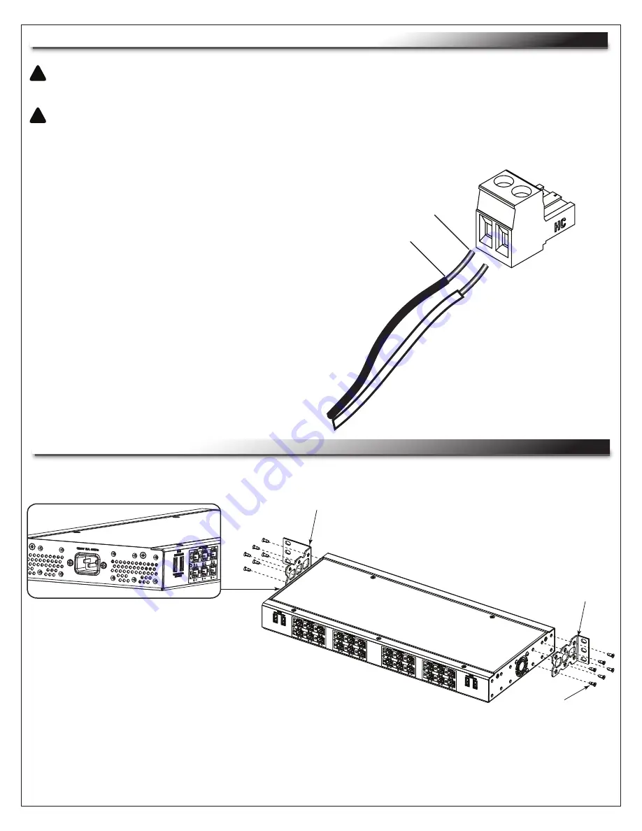
MAKING TERMINAL BLOCK CONNECTIONS

!

!

CAUTION: 

Use a multimeter to confirm wire polarity before making

connnections or damage to equipment may occur.

ATTENTION: 

Utiliser un multimètre pour confirmer la polarité des 

fils avant d'effectuer la connexion ou des dommages à l'équipement 

peut se produire. 

1. Strip 1/4” of insulation from wire ends. 

(FIGURE A)

2. Determine correct polarity of po and negative - 

  wire ends.

3. Select appropriate color-coded terminal block:

  A. Orange = 5V DC

  B. Yellow = 12V DC

  C. Blue = 18V DC

  D. Red = 24V DC

4. Insert bare wire ends into terminal block.

5. Tighten connections securely with screwdriver.

6. Insert terminal block into appropriate power bank.

1/4”

+

+

-

-

FIGURE A

RACK EAR INSTALLATION

1. Install rack ears as shown using supplied rack ear screws. 

(FIGURE B)

2. Rack ears may be installed in a variety of orientations. For more information, see Rack Ear Mounting

  Orientation on page 8.

FIGURE B

F

H

E

NOTE: 

The longer rack ear (E) is 

installed on the side containing 

the IEC socket.

Summary of Contents for PD-DC-125R

Page 1: ...asing the PD DC 125R PRODUCT FEATURES THANK YOU Multi voltage support 5 12 18 24V Surge and overload protection Adjustable mounting ears for flexible installation options Four 5V USB Charging Ports TOTAL 5V 2 5A ALL USB STATUS STATUS STATUS STATUS PD DC 125R ACTIVE OVERLOAD SHUTDOWN STATUS ...

Page 2: ... to operate the equipment NOTE This equipment has been tested and found to comply with the limits for a Class B digital device pursuant to part 15 of the FCC Rules These limits are designed to provide reasonable protection against harmful interference in a residential installation This equipment generates uses and can radiate radio frequency energy and if not installed and used in accordance with ...

Page 3: ...ed to dripping or splashing and that no objects filled with liquids such as vases shall be placed on the apparatus 13 The mains plug is used as your disconnect device This device shall remain readily operable 14 Clean only with dry cloth 15 Unplug this apparatus during lightning storms or when unused for long periods of time 16 Only use attachments accessories specified by the manufacturer 17 Do n...

Page 4: ...2 AVERTISSEMENT L appareil ne doit pas être exposé à des éclaboussures et aucun objet rempli de liquide comme des vases ne doit être placé sur l appareil 13 La fiche secteur est utilisée comme sectionneur de courant Ce dispositif doit rester en état de marche 14 Nettoyer uniquement avec un chiffon sec 15 Débrancher cet appareil pendant les orages ou s il n est pas utilisé pendant de longues périod...

Page 5: ...ARDWARE KIT INCLUDES Orange 5V DC Connector Yellow 12V DC Connector Blue 18V DC Connector Red 24V DC Connector Standard Mount Ears Deep Rack Mount Ears Rack Ear Screws QTY DESCRIPTION 6 6 6 6 2 2 12 ITEM A B C D E F G A B C D G E F H ...

Page 6: ... SIX OUTPUTS Individually protected by automatically resettable PTC Fuses Short circuit and overload protection F 24V DC 1 2A BANK SIX OUTPUTS Individually protected by automatically resettable PTC Fuses Short circuit and overload protection G BANK OVER CURRENT WARNING LIGHT Green OK Amber Approaching current limit of power bank shutdown imminent H IEC C 14 POWER INPUT 120VAC 5A 60HZ I OUTPUT POWE...

Page 7: ...and negative wire ends 3 Select appropriate color coded terminal block A Orange 5V DC B Yellow 12V DC C Blue 18V DC D Red 24V DC 4 Insert bare wire ends into terminal block 5 Tighten connections securely with screwdriver 6 Insert terminal block into appropriate power bank 1 4 FIGURE A RACK EAR INSTALLATION 1 Install rack ears as shown using supplied rack ear screws FIGURE B 2 Rack ears may be inst...

Page 8: ...OUNTING VERTICAL MOUNTING All ears can be mounted facing front or rear of unit Standard depth mount ears pictured Deep rack mount ears can be mounted facing front or rear of unit All ears can be mounted facing up or down front or rear of unit Standard depth mount ears pictured ...

Page 9: ... 108VAC MAX 127VAC 5A AC 600W DC OUTPUTS FULLY LOADED IEC C 14 6 Feet MOV MODE L N CLAMPING VOLTAGE 595V 11 2A DC 125 3W Automatically Resetting PTC Fused On Each Output 250A AC VOLTAGE 5V DC 12V DC 18V DC 24V DC USB 5VDC MAX CURRENT TOTAL RAIL 3A 2A 2 5A 1 2A 2 5A MAX CURRENT PER OUTPUT RAIL CURRENT WARNING 2A 1 5A 1A 75 2 1A 2 85A 1 9A 2 25A 1 15A N A DC OUTPUTS CAUTION Do not exceed maximum rat...

Page 10: ...OF ANY KIND EITHER EXPRESSED OR IMPLIED INCLUDING BUT NOT LIMITED TO IMPLIED WARRANTIES OF MERCHANTABILITY AND FITNESS FOR A PARTICULAR PURPOSE TO THE MAXIMUM EXTENT PERMITTED BY APPLICABLE LAW IN NO EVENT SHALL THE COMPANY BE LIABLE FOR ANY SPECIAL INCIDENTAL INDIRECT OR CONSEQUENTIAL DAMAGES WHATSOEVER INCLUDING WITHOUT LIMITATION DAMAGES FOR LOSS OF BUSINESS PROFITS BUSINESS INTERRUPTION OR ANY...

Reviews: