Chapter 1: Introduction
13
Front Panel (Rackmount PDUs Only)
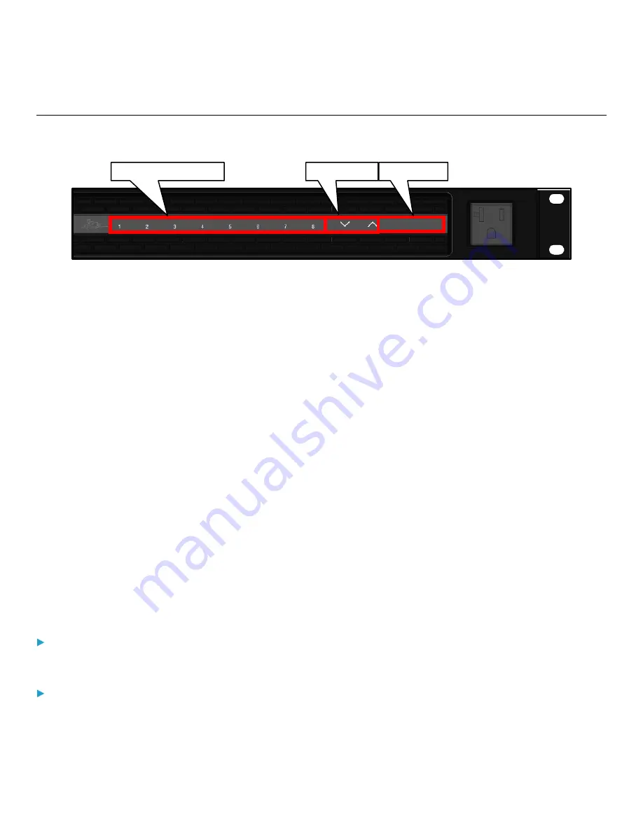
The following diagram shows the front panel layout.
You can use the front panel to view PDU information and even switch an outlet. It consists of:
•
(8x) outlet buttons
•
(2x) control buttons
•
A front panel display
Viewing PDU Information on the Front Panel Display
The front panel display shows the MAIN MENU which includes the following measurements in this specific order:
1.
INPUT VOLTAGE Title
Input Voltage Measurement (example: 120.7 VOLTS)
2.
ALARMS Title
Alarm Amount or Value (example: NO ALARMS or 2 ALARMS)
3.
TEMPERATURE Title
Temperature Sensor Measurement (example: 78.3 F)
4.
ACTIVE POWER Title
Active Power Measurement (example: 458.7 WATTS)
5.
CURRENT DRAW Title
Current Draw Measurement (example: 3.8 AMPS)
Normal Operation:
•
During normal operation, the front panel display cycles through items 1-5 with a 2 second delay.
Pressing Control Buttons:
•
Pressing a control button will step you through the titles. After no control button is pressed for 2 seconds, the display
will resume the normal operation display cycle.
Outlet Buttons and LEDs
Control Buttons
Display Area


