background image

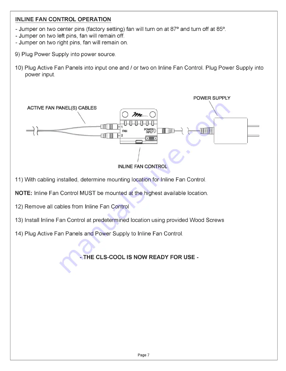
INLINE  FAN  CONTROL OPERATION

- Jumper on two  center pins  (factory setting) fan will turn on  at 87° and turn  off at 85°.
- Jumper on two  left  pins,  fan will  remain  off.
- Jumper on two  right pins,  fan will  remain  on.

9)  Plug  Power Supply  into power source.

10)  Plug Active  Fan  Panels  into  input one and / or two on  Inline  Fan  Control.  Plug  Power Supply  into 

power  input.

ACTIVE  FAN  PANEL(S) CABLES

POW ER SUPPLY

U

INLINE  FAN  CONTROL

11) With cabling  installed,  determine  mounting  location for  Inline  Fan  Control.

NOTE: 

Inline  Fan  Control  MUST be  mounted  at the  highest available  location.

12)  Remove all  cables from  Inline  Fan  Control

13)  Install  Inline  Fan  Control  at  predetermined  location  using  provided Wood  Screws

14)  Plug Active  Fan  Panels  and  Power Supply to  Inline  Fan  Control.

- THE  CLS-COOL  IS  NOW READY FOR USE  -

Page  7

Summary of Contents for QUIET-COOL CLS-COOL1

Page 1: ...s CLS COOL Closet Cooler Please read these instructions thoroughly thoroughly before installing assembling this product PRODUCT FEATURES Extends equipment life Quietly removes heat produced by electronic equipment Thermostatically controlled fans run only when necessary Attractive solid oak vents can be stained or painted to match any decor Middle Atlantic Products I 00219 Rev B ...

Page 2: ...EL CLS COOL1 BOTTOM PANEL 1 11 16 42mm 15 3 4 399mm 1 11 16 42mm r 4 1 16 103 mm FRONT SIDE FRONT SIDE ACTIVE REAR PANEL CLS COOL1 ACTIVE EXHAUST PANEL CLS COOL2 ACTIVE EXHAUST INTAKE PANEL PASSIVE REAR PANEL CLS COOL1 PASSIVE INTAKE PANEL 15 3 4 399mm T 5 3 4 146 mm _ L FRONT 1 J SIDE _ 1 1 4 31 mm 15 3 4 399mm f 4 1 16 103mm ___ L _ 9 16 15mm FRONT SIDE INLINE FAN CONTROL TOOLS REQUIRED DRILL 3 ...

Page 3: ... CLS COOL2 QTY PLEASE READ A ll INSTRUCTIONS BEFORE UStff THIS TEhFLATE _________ II___________ ACTIVE EXHAUST PANEL 12 ft cord QTY WIRE TIE MOUNT CLS COOL1 CLS COOL2 O WIRE TIE CLS COOL1 CLS COOL2 INLINE FAN CONTROL CLS COOL1 CLS COOL2 POWER SUPPLY CLS COOL1 CLS COOL2 in n i j WOOD SCREW 6x3 8 CLS COOL1 CLS COOL2 SCREW 10 32x2 CLS COOL1 CLS COOL2 SCREW 10 32x1 1 2 CLS COOL1 CLS COOL2 Page 3 QTY 5...

Page 4: ...ssive Intake installation 2 Using center lines as a guide trace template on upper section of the door Mark four outer corner holes on the template 3 Using a 3 8 drill bit drill 4 clearance holes at pre marked corner holes to allow access for jigsaw 4 Carefully cut out traced section of door 5 Repeat steps 2 4 for the Passive or Active Intake NOTE For CLS COOL1 Passive Intake cut the template as it...

Page 5: ...ive Exhaust Panel Use two 10 32x1 5 screws For CLS COOL2 use eight 10 32x2 screws to attach Active Intake Panel and Active Exhaust Panel A SNUG SCREWS EVENLY A ACTIVE EXHAUST PANEL PASSIVE INTAKE PANEL CLS COOL1 REVIEW ACTIVE EXHAUST PANEL ACTIVE INTAKE PANEL CLS COOL2 REVIEW TIP If using a raised or recessed panel door cosmetic fillers or trimming may be required COSMETIC FILLER MOLDING TRIM Page...

Page 6: ......

Page 7: ...nline Fan Control Plug Power Supply into power input ACTIVE FAN PANEL S CABLES POWER SUPPLY U INLINE FAN CONTROL 11 With cabling installed determine mounting location for Inline Fan Control NOTE Inline Fan Control MUST be mounted at the highest available location 12 Remove all cables from Inline Fan Control 13 Install Inline Fan Control at predetermined location using provided Wood Screws 14 Plug ...

Page 8: ...ANY KIND EITHER EXPRESSED OR IMPLIED INCLUDING BUT NOT LIMITED TO IMPLIED WARRANTIES OF MERCHANTABILITY AND FITNESS FOR A PARTICULAR PURPOSE TO THE MAXIMUM EXTENT PERMITTED BY APPLICABLE LAW IN NO EVENT SHALL THE COMPANY BE LIABLE FOR ANY SPECIAL INCIDENTAL INDIRECT OR CONSEQUENTIAL DAMAGES WHATSOEVER INCLUDING WITHOUT LIMITATION DAMAGES FOR LOSS OF BUSINESS PROFITS BUSINESS INTERRUPTION OR ANY OT...

Reviews: