2
Table of Contents
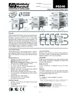
Spec Sheet .............................................................................................................................................. 3
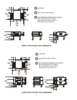
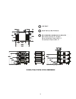
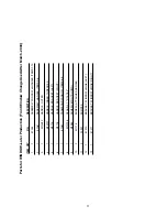
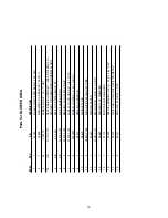
Oven and Electrical Specifications .......................................................................................................... 6
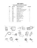
Key Parts ................................................................................................................................................. 7
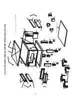
View of Oven Panels, Window and Legs (Earlier Production) ................................................................. 8
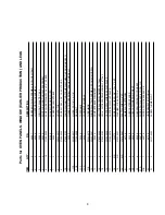
Parts for Oven Panels, Window and Legs (Earlier Production ................................................................ 9
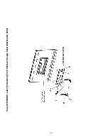
View of Oven Panels, Window and Legs (Later Production) ................................................................. 10
Parts for Oven Panels, Window and Legs (Later Production ................................................................ 11
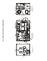
View of Right-hand Control Compartment .............................................................................................. 12
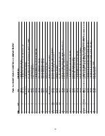
Parts for Right-hand Control Compartment ............................................................................................ 13
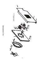
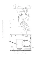
View of Blower Area ............................................................................................................................... 14
Parts for Blower Area ............................................................................................................................. 15
View of Blower/Motor Compartment ....................................................................................................... 16
Parts for Blower/Motor Compartment ..................................................................................................... 17
View of Gas Burner & Piping ................................................................................................................. 18
Parts for Gas Burner & Piping ............................................................................................................... 19
View of “Single” Belt Conveyor .............................................................................................................. 20
Parts for “Single” Belt Conveyor ............................................................................................................ 21
View of “Split” Belt Conveyor ................................................................................................................. 22
Parts for “Split” Belt Conveyor ............................................................................................................... 23
PS540G OVEN INSTALLATION KIT .................................................................................................... 24
PS540G Single Oven Option Base Kit ................................................................................................... 25
PS540G Double Oven Option Base Kit ................................................................................................. 26
PS540G Triple Oven Option Base Kit (Outriggers) ............................................................................... 27
Standard Finger Configuration ............................................................................................................... 28
Wiring Diagram, 208-240 volt 50/60 Hz, 1 Phase 3W 50141 Rev. F2 US/UK/CANADA ...................... 29
Ladder Wiring Diagram, 208-240 volt 50/60 Hz, 1 Phase 3W 50141 Rev. F1 US/UK/CANADA .......... 30
Wiring Diagram, 208-240 volt 50/60 Hz, 1 Phase 3W 52059 Rev. D DN .............................................. 31
Wiring Diagram, 208-240 volt 50/60 Hz, 1 Phase 3W 52065 Rev. D DUT ............................................ 32
Wiring Diagram, 208-240 volt 50/60 Hz, 1 Phase 3W 52053 Rev. D FR ............................................... 33
Wiring Diagram, 208-240 volt 50/60 Hz, 1 Phase 3W 52055 Rev. D GM .............................................. 34
Wiring Diagram, 208-240 volt 50/60 Hz, 1 Phase 3W 52067 Rev. D GK .............................................. 35
Wiring Diagram, 208-240 volt 50/60 Hz, 1 Phase 3W 52061 Rev. D IT ................................................. 36
Wiring Diagram, 208-240 volt 50/60 Hz, 1 Phase 3W 52057 Rev. D SP ............................................... 37
Wiring Diagram, 208-240 volt 50/60 Hz, 1 Phase 3W 52063 Rev. D SW .............................................. 38
Summary of Contents for PS540-1
Page 3: ...3 ...
Page 8: ...8 View of OVEN PANELS WINDOW EARLIER PRODUCTION AND LEGS ...
Page 10: ...10 View of WINDOW Later Production Front Window Change Used After March 2004 ...
Page 12: ...12 View of RIGHT HAND CONTROL COMPARTMENT ...
Page 14: ...14 View of BLOWER AREA 3A NOT SHOWN NEVER SEIZE LUBRICANT ...
Page 16: ...16 View of BLOWER MOTOR COMPARTMENT ...
Page 20: ...20 View of Single Belt Conveyor 39 NOT SHOWN HEYCO PLIERS ...
Page 22: ...22 View of Split Belt Conveyor 42 NOT SHOWN HEYCO PLIERS ...
Page 31: ...31 Middleby PS540G Wiring Diagram 208 240 volt 50 60 Hz 1 Phase 3W DN 52059D ...
Page 32: ...32 Middleby PS540G Wiring Diagram 208 240 volt 50 60 Hz 1 Phase 3W DUT 52065D ...
Page 33: ...33 Middleby PS540G Wiring Diagram 208 240 volt 50 60 Hz 1 Phase 3W FR 52053D ...
Page 34: ...34 Middleby PS540G Wiring Diagram 208 240 volt 50 60 Hz 1 Phase 3W GM 52055D ...
Page 35: ...35 Middleby PS540G Wiring Diagram 208 240 volt 50 60 Hz 1 Phase 3W GK 52067D ...
Page 36: ...36 Middleby PS540G Wiring Diagram 208 240 volt 50 60 Hz 1 Phase 3W IT 52061D ...
Page 37: ...37 Middleby PS540G Wiring Diagram 208 240 volt 50 60 Hz 1 Phase 3W SP 52057D ...
Page 38: ...38 Middleby PS540G Wiring Diagram 208 240 volt 50 60 Hz 1 Phase 3W SW 52063D ...
Page 39: ...39 NOTES ...
Page 40: ...40 ...


