7
KEY PARTS
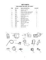
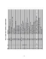
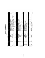
PS540-SERIES GAS OVEN KEY PARTS
ITEM
PART NO.
ENGLISH DESCRIPTION
QUANTITY
1
58504
Temperature Controller
1
2
44687
Blower/Fan Motor
1
3
47797
Conveyor Drive Motor, Standard Speed
1 or 2
3A
47799
Conveyor Drive Motor, High Speed
1 or 2
3B
45017
Kit, Brushes, Springs & Caps
1
3C
50265
Pickup, Sensor
1
4
58323
Conveyor Speed Control
1
5
33812-3
Thermocouple
3
6
41647
Modulating Gas Valve
1
7
50275
Burner & Motor Assembly
1
8
50239
Ignition Control Module (kit)
1
9
See RPM Kit
Blower Belt, page 17
1
10
33983
High Limit Control Module
1
11
36451
Cooling Fan
2
12
50610
Air Switch
2
13
50274
Control Valve, Gas, 1/2"
1
14
31651
Signal Amplifier
1
1
2
3
4
5
6
7
8
9
10
11
12
13
14
Summary of Contents for PS540-1
Page 3: ...3 ...
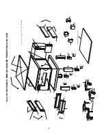
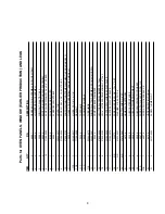
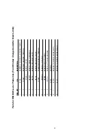
Page 8: ...8 View of OVEN PANELS WINDOW EARLIER PRODUCTION AND LEGS ...
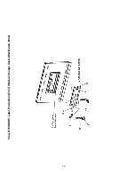
Page 10: ...10 View of WINDOW Later Production Front Window Change Used After March 2004 ...
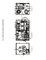
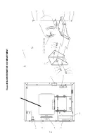
Page 12: ...12 View of RIGHT HAND CONTROL COMPARTMENT ...
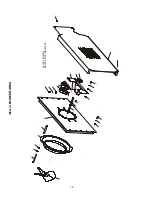
Page 14: ...14 View of BLOWER AREA 3A NOT SHOWN NEVER SEIZE LUBRICANT ...
Page 16: ...16 View of BLOWER MOTOR COMPARTMENT ...
Page 20: ...20 View of Single Belt Conveyor 39 NOT SHOWN HEYCO PLIERS ...
Page 22: ...22 View of Split Belt Conveyor 42 NOT SHOWN HEYCO PLIERS ...
Page 31: ...31 Middleby PS540G Wiring Diagram 208 240 volt 50 60 Hz 1 Phase 3W DN 52059D ...
Page 32: ...32 Middleby PS540G Wiring Diagram 208 240 volt 50 60 Hz 1 Phase 3W DUT 52065D ...
Page 33: ...33 Middleby PS540G Wiring Diagram 208 240 volt 50 60 Hz 1 Phase 3W FR 52053D ...
Page 34: ...34 Middleby PS540G Wiring Diagram 208 240 volt 50 60 Hz 1 Phase 3W GM 52055D ...
Page 35: ...35 Middleby PS540G Wiring Diagram 208 240 volt 50 60 Hz 1 Phase 3W GK 52067D ...
Page 36: ...36 Middleby PS540G Wiring Diagram 208 240 volt 50 60 Hz 1 Phase 3W IT 52061D ...
Page 37: ...37 Middleby PS540G Wiring Diagram 208 240 volt 50 60 Hz 1 Phase 3W SP 52057D ...
Page 38: ...38 Middleby PS540G Wiring Diagram 208 240 volt 50 60 Hz 1 Phase 3W SW 52063D ...
Page 39: ...39 NOTES ...
Page 40: ...40 ...


