Service Manual_2018-V2.0
33
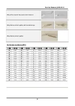
9.4 Sensor resistance (R/T)
Tx(
℃
)
R
(
K
Ω
)
Tx(
℃
)
R
(
K
Ω
)
Tx(
℃
)
R
(
K
Ω
)
Tx(
℃
)
R
(
K
Ω
)
Tx(
℃
)
R
(
K
Ω
)
-30
33.81
-15
14.31
0
6.495
15
3.141
30
1.617
-29
31.85
-14
13.55
1
6.175
16
2.999
31
1.55
-28
30.01
-13
12.83
2
5.873
17
2.865
32
1.486
-27
28.29
-12
12.16
3
5.587
18
2.737
33
1.426
-26
26.68
-11
11.52
4
5.315
19
2.616
34
1.368
-25
25.17
-10
10.92
5
5.06
20
2.501
35
1.312
-24
23.76
-9
10.35
6
4.818
21
2.391
36
1.259
-23
22.43
-8
9.82
7
4.589
22
2.287
37
1.209
-22
21.18
-7
9.316
8
4.372
23
2.188
38
1.161
-21
20.01
-6
8.841
9
4.167
24
2.094
39
1.115
-20
18.9
-5
8.392
10
3.972
25
2.005
40
1.071
-19
17.87
-4
7.968
11
3.788
26
1.919
41
1.029
-18
16.9
-3
7.568
12
3.613
27
1.838
42
0.9885
-17
15.98
-2
7.19
13
3.447
28
1.761
43
0.9506
-16
15.12
-1
6.833
14
3.29
29
1.687
44
0.914
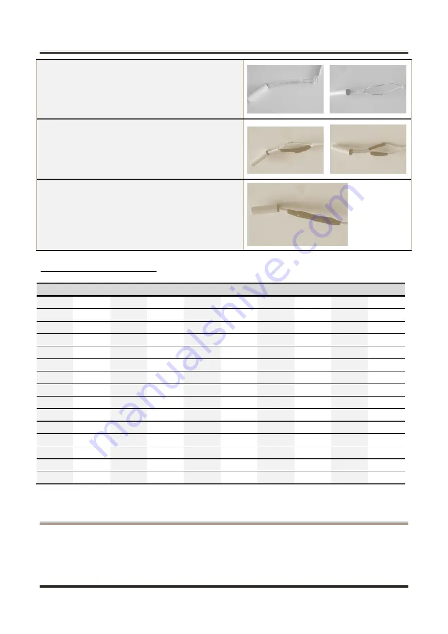
Strip off the head of the sensor and connect it.
Wrap the two wires together with insulation tape.
Wrap the two wires together.
Summary of Contents for 22031020003641
Page 5: ...Service Manual_2018 V2 0 5 1 Significant update notes None...
Page 18: ...Service Manual_2018 V2 0 18 6 5Main control board schematic diagram...
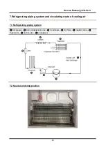
Page 20: ...Service Manual_2018 V2 0 20 7 3 Circulating route of cooling air...
Page 38: ...Service Manual_2018 V2 0 38 12 Troubleshooting Method 12 1 No cooling Air cooling Electronic...
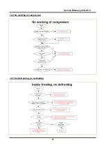
Page 39: ...Service Manual_2018 V2 0 39 12 2 No working of compressor 12 3 Inside frosting no defrosting...
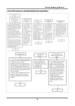
Page 40: ...Service Manual_2018 V2 0 40 12 4 Inside frosting no defrosting Maintenance guidelines...
Page 41: ...Service Manual_2018 V2 0 41 12 5 Light is not on 12 6 Fan failure...
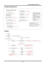
Page 42: ...Service Manual_2018 V2 0 42 12 7 Defective defrost circuit 12 8 Noise...
Page 43: ...Service Manual_2018 V2 0 43 12 9 Air duct not operated electronically None...
Page 44: ...Service Manual_2018 V2 0 44 13 Figures and details of repair parts See this section in the TSP...

