background image

Aqua Tempo Power Series (with LAK) air cooled scroll chiller unit (50Hz)                                                      MCAC-ATSM-2013-11 


Content 


1 General information ................................................................................ 1


2 Features .................................................................................................... 3


3 Specifications .......................................................................................... 7


4 Dimensions ............................................................................................ 17


5 Refrigeration System Drawings ........................................................... 23


6 Piping Diagrams .................................................................................... 26


7 Wire Diagrams ........................................................................................ 32


8 Electric Characteristics ......................................................................... 46


9 Capacity Tables ...................................................................................... 48


10 Exploded Views ................................................................................... 58


11 Troubleshooting ................................................................................... 82


12 Installation ............................................................................................ 98


13 Commissioning .................................................................................. 125


14 Maintenance ....................................................................................... 126


15 Control System .................................................................................. 130


16 Optional Accessories ........................................................................ 202


Appendix ................................................................................................. 202 


Manufacture reserves  the  right  to  discontinue,  or change  at  any  time,  specifications or designs  without  notices and  without 

incurring obligations. 


Summary of Contents for Aqua Tempo Super Series

Page 1: ...6 Piping Diagrams 26 7 Wire Diagrams 32 8 Electric Characteristics 46 9 Capacity Tables 48 10 Exploded Views 58 11 Troubleshooting 82 12 Installation 98 13 Commissioning 125 14 Maintenance 126 15 Con...

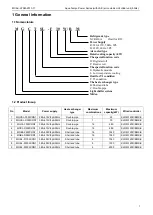
Page 2: ...5 MGBL F65W RN1 380 400V 3ph 50Hz Shell and tube 16 1040 KJRM 120D BMK E 6 MGBL D65W RN1 380 415V 3ph 50Hz Shell and tube 16 1040 KJRM 120D BMK E 7 MGBL F130W RN1 380 400V 3ph 50Hz Shell and tube 8 10...

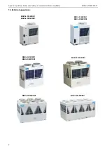
Page 3: ...s with LAK air cooled scroll chiller unit 50Hz MCAC ATSM 2013 11 2 1 3 External appearance MGCSL F30W RN1 MGCSL D30W RN1 MGBL F130W RN1 MGBL F200W RN1 MGBL F250W RN1 MGCL F30W RN1 MGCL D30W RN1 MGBL F...

Page 4: ...cooling and heating capacity output basing on actual requirement of the indoor room Digital scroll technique provide maximum reliability high efficiency and quiet operation 4 Modular design flexible...

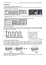
Page 5: ...ion happens this unit will stop but the others will keep running If slave unit s protection happens this unit will stop but the others will keep running Except PE P9 protection happens PE Low temperat...

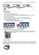
Page 6: ...cost savings Easy to transport No need cooling water tower 11 Reliable protections Many kinds of protection are adopted to make sure the safe running for chiller 12 Super reliability System will be mo...

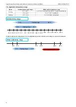
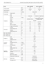
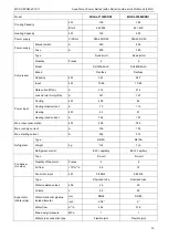
Page 7: ...C must add antifreeze 10 C 46 C 5 C 17 C 7 C is default Heating 10 C 21 C 22 C 50 C 45 C is default Chilled outlet water temperature can be adjusted by wired controller according to customer s demand...

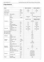
Page 8: ...kW 10 1 2 pump 10 1 2 pump Cooling rated current A 16 3 16 3 Heating kW 9 8 1 2 pump 9 8 1 2 pump Heating rated current A 16 16 Max input consumption kW 13 4 Max running current A 25 3 Max starting c...

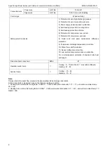
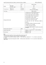
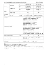
Page 9: ...Control type Wired controller Safety protection device 1 Protection for over high discharge pressure 2 Protection for over low suction pressure 3 Power supply phase sequence protection 4 Anti freezing...

Page 10: ...tor Amp LRA A 74 74 74 Power input Cooling kW 10 0 10 0 Cooling rated current A 16 3 16 3 Heating kW 9 8 9 8 Heating rated current A 16 16 Max input consumption kW 12 6 Max running current A 21 1 Max...

Page 11: ...0 4 6 1 Signal wire mm 2 No 0 75 3 core with shielding Control type Wired controller Safety protection device 1 Protection for over high discharge pressure 2 Protection for over low suction pressure 3...

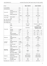
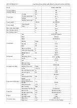
Page 12: ...Capacity kW 34 7 35 4 16 848 16 2 Input kW 10 86 10 8 5 75 5 2 Rate current RLA A 21 4 21 1 12 7 11 8 Locked rotor Amp LRA A 147 144 82 4 74 Refrigerant Type R410A R410A Refrigerant control EXV capil...

Page 13: ...e protection 9 Compressor discharge temperature protection 10 Water flow cut off protection 11 Sensor malfunction protection 12 Low ambient temperature drive up protection 13 Low temperature protectio...

Page 14: ...er input Cooling kW 40 8 63 Cooling rated current A 73 110 Heating kW 43 61 Heating rated current A 74 4 107 Max input consumption kW 55 5 78 3 Max running current A 109 150 Max starting current A 252...

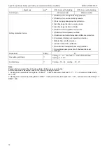
Page 15: ...in Winter 6 Protection for compressor over current 7 Protection for compressor overload 8 Outlet and inlet water temperature difference protection 9 Compressor discharge temperature protection 10 Wat...

Page 16: ...20 7 Locked rotor Amp LRA A 142 Refrigerant oil ml 3300 Refrigerant Type R410A Refrigerant control EXV capillary Weight kg 15 4 Condenser Air side Type Fin coil Number of rows 3 Fan motor model YDK55...

Page 17: ...ure protection 10 Water flow cut off protection 11 Sensor malfunction protection 12 Low ambient temperature drive up protection 13 Low temperature protection of shell and tube heat exchanger Noise lev...

Page 18: ...er unit 50Hz 17 4 Dimensions 30kW module Front view Top view Model Unit A B C D E F MGCL F30W RN1 MGCL D30W RN1 mm 1514 841 1865 115 315 172 inch 59 6 33 11 73 43 4 53 12 4 6 77 No Name 1 Top cover 2...

Page 19: ...led scroll chiller unit 50Hz MCAC ATSM 2013 11 18 30kW module MGCSL F30W RN1 MGCSL D30W RN1 1865 874 317 Front view Left view Top view 1 1 2 4 5 6 3 NO NAME 1 2 3 4 5 6 Air outlet Air inlet Water outl...

Page 20: ...Model Unit A B C D E F G H I J K MGBL F65W RN1 MGBL D65W RN1 mm 2000 900 1880 350 1420 225 1500 506 530 930 450 inch 78 74 35 4 74 13 78 55 91 8 86 59 06 19 92 20 87 36 61 17 72 130kW module Front vie...

Page 21: ...Top view Anchor hole Model Unit A B C D E F G H MGBL F130W RN1 mm 2000 1685 2080 350 1420 506 1550 1586 inch 78 74 66 34 81 89 13 78 55 91 19 92 61 02 62 44 No Name 1 Top cover 2 Condenser 3 Compresso...

Page 22: ...r unit 50Hz 21 200kW module Model unit A B C D E F G H MGBL F200W RN1 Mm 2850 2000 2110 3470 2156 506 1888 2388 inch 112 2 78 74 83 07 136 61 84 88 19 92 74 33 94 02 No Name 1 Top cover 2 Compressor 3...

Page 23: ...74 83 86 48 62 84 88 22 56 74 33 61 06 Front view E A C F D No Name 1 Top cover 2 Compressor 3 Evaporator 4 Water outlet 5 Electric control box 6 Water inlet 7 Condenser 8 Transportation guard plate...

Page 24: ...cylinder A Low pressure cylinder B 4 way valve A 4 way valve B Condenser Evaporator Double pipe heat exchanger Fan Water outlet Water inlet EXV EXV 5 2 65kW module MGBL F60W RN1 Each module has two c...

Page 25: ...tems Dry type evaporator Condenser Water flow direction Compressor B low pressure cylinder B 4 Way valve A Fan A EXV Capillary EXV 2 1 2 Unit 2 Capillary Fan B 4 Way valve B Compressor A low pressure...

Page 26: ...er B 4 Way valve A Fan A EXV Capillary EXV 3 Unit 2 Unit 3 Capillary Fan B 4 Way valve B Compressor A low pressure cylinder A Unit 1 5 5 250kW module Each module has eight compressors with two separat...

Page 27: ...Diagrams 6 1 30kW module water pipeline sketch drawing The table below describes the symbols Symbol Symbol explanation Symbol Symbol explanation Stop valve Y shaped filter Pressure gauge Thermometer...

Page 28: ...odule water pipeline sketch drawing For MGCSL F D 30W RN1 The table below describes the symbols Symbol Symbol explanation Symbol Symbol explanation Safety valve Y shaped filter Pressure gauge Thermome...

Page 29: ...ol Symbol explanation Symbol Symbol explanation Stop valve Y shaped filter Pressure gauge Thermometer Water flow switch Circulating pump Gate valve Check valve Flexible joint Automatic discharge valve...

Page 30: ...6 3 130kW module water pipeline sketch drawing The table below describes the symbols Symbol Symbol explanation Symbol Symbol explanation Stop valve Y shaped filter Pressure gauge Thermometer Water flo...

Page 31: ...6 4 200kW module water pipeline sketch drawing The table below describes the symbols Symbol Symbol explanation Symbol Symbol explanation Stop valve Y shaped filter Pressure gauge Thermometer Water flo...

Page 32: ...6 5 250kW module water pipeline sketch drawing The table below describes the symbols Symbol Symbol explanation Symbol Symbol explanation Stop valve Y shaped filter Pressure gauge Thermometer Water flo...

Page 33: ...MCAC ATSM 2013 11 Aqua Tempo Power Series with LAK air cooled scroll chiller unit 50Hz 32 7 Wire Diagrams 7 1 Wiring diagrams 30kW module...

Page 34: ...D U L E O N OF F S IG N A L L OW V O L T A GE SI G N AL D O N T C O N N E CT H I GH V OLT A G E P R O V I D E B Y U S E R P R O V I D E B Y U S E R O N OF F S I G NA L 2 WAY TERMINAL XT3 11 WAY TERMIN...

Page 35: ...Aqua Tempo Power Series with LAK air cooled scroll chiller unit 50Hz MCAC ATSM 2013 11 34 65kW module MGBL F65W RN1...

Page 36: ...MCAC ATSM 2013 11 Aqua Tempo Power Series with LAK air cooled scroll chiller unit 50Hz 35 65kW module MGBL D65W RN1...

Page 37: ...Aqua Tempo Power Series with LAK air cooled scroll chiller unit 50Hz MCAC ATSM 2013 11 36 130kW module...

Page 38: ...MCAC ATSM 2013 11 Aqua Tempo Power Series with LAK air cooled scroll chiller unit 50Hz 37 200kW module...

Page 39: ...Aqua Tempo Power Series with LAK air cooled scroll chiller unit 50Hz MCAC ATSM 2013 11 38 250kW module...

Page 40: ...MCAC ATSM 2013 11 Aqua Tempo Power Series with LAK air cooled scroll chiller unit 50Hz 39 7 2 Networking communication schematic of main unit and auxiliary unit 30kW module...

Page 41: ...heater and pump is just for reference please follow the instructions of corresponding auxiliary heater products Please choose such accessory as power wire switch of auxiliary heater according to the...

Page 42: ...e n g t h o f w i r e s hould be shorter t han 500m 1 00 Black Yellow Gray Query Fault Notes The wiring diagram of auxiliary heater and pump is just for reference please follow the instructions of cor...

Page 43: ...gt h of wir e s h ou ld be s ho rt er t h an 50 0m 1 00 Black Yellow Gray Query Fault Notes The wiring diagram of auxiliary heater and pump is just for reference please follow the instructions of cor...

Page 44: ...o r r e f e r e n ce p l e a se f o l l o w t he i n str u c ti o n s o f c o rr esp o n di n g a u x i l i a r y h eat e r p r o du c t s P l e as e c h o o s e s u ch a c c e s s o r y as p o we r w...

Page 45: ...Aqua Tempo Power Series with LAK air cooled scroll chiller unit 50Hz MCAC ATSM 2013 11 44 200kW module...

Page 46: ...e corresponding to the Terminal P Q and E of Wiring Board in Main Module Black Yello w Gray Power Supply Connector N o t es T he wi r i ng di a g r am of au x i l i a ry h e a t er and pu mp is j u st...

Page 47: ...11 8 0 67 3 1 MGCL D30W RN1 50 380 415 342 456 21 1 36 74 10 6 11 8 0 67 3 1 MGBL F65W RN1 50 380 400 342 440 54 5 70 147 21 4 0 865 2 4 0 2 MGBL D65W RN1 50 380 415 342 456 54 5 70 144 82 4 74 21 1...

Page 48: ......

Page 49: ...0 9 70 30 00 10 00 28 17 10 50 25 97 11 03 8 00 37 04 9 40 34 78 9 69 32 72 9 99 30 84 10 30 28 99 10 82 26 76 11 36 9 00 38 09 9 49 35 73 9 79 33 58 10 09 31 62 10 40 29 75 10 92 27 49 11 47 10 00 39...

Page 50: ...56 43 00 18 22 6 52 22 86 7 40 26 98 8 23 30 08 8 94 32 80 9 41 36 54 9 98 41 81 10 77 44 00 17 86 6 65 22 44 7 55 26 53 8 39 29 61 9 12 32 32 9 60 35 94 10 18 41 04 10 99 45 00 17 60 6 78 22 14 7 71...

Page 51: ...00 20 40 61 04 21 42 56 27 22 49 8 00 80 26 19 18 75 36 19 77 70 90 20 38 66 82 21 01 62 81 22 06 57 97 23 17 9 00 82 52 19 36 77 41 19 96 72 76 20 58 68 51 21 22 64 47 22 28 59 57 23 39 10 00 85 65...

Page 52: ...0 39 28 14 29 49 28 16 24 58 18 18 05 64 86 19 62 70 74 20 65 78 80 21 89 90 15 23 64 44 00 38 52 14 58 48 39 16 57 57 20 18 42 63 84 20 02 69 69 21 07 77 50 22 33 88 50 24 12 45 00 37 96 14 88 47 75...

Page 53: ...42 84 112 55 44 98 8 00 160 52 38 35 150 72 39 54 141 79 40 76 133 64 42 02 125 62 44 13 115 95 46 33 9 00 165 05 38 73 154 83 39 92 145 52 41 16 137 02 42 43 128 94 44 55 119 14 46 78 10 00 171 31 3...

Page 54: ...59 98 56 32 48 116 37 36 09 129 73 39 23 141 47 41 30 157 60 40 72 180 29 43 98 44 00 77 03 29 17 96 78 33 15 114 39 36 83 127 67 40 03 139 38 42 14 154 99 41 55 177 00 44 88 45 00 75 92 29 76 95 49...

Page 55: ...66 15 160 17 69 46 8 00 228 44 59 22 214 49 61 06 201 78 62 94 190 18 64 89 178 77 68 13 165 00 71 54 9 00 234 87 59 80 220 33 61 65 207 08 63 55 194 99 65 52 183 49 68 80 169 54 72 24 10 00 237 19 6...

Page 56: ...2 84 46 08 168 65 51 20 188 01 55 66 205 03 58 58 228 40 62 10 261 29 67 07 44 00 111 64 41 38 140 26 47 02 165 79 52 25 185 03 56 79 202 00 59 78 224 62 63 37 256 52 68 44 45 00 110 03 42 22 138 40 4...

Page 57: ...5 82 22 216 44 86 33 8 00 308 70 73 61 289 86 75 88 272 68 78 23 257 00 80 65 241 58 84 68 222 98 88 92 9 00 317 40 74 32 297 75 76 62 279 84 78 99 263 50 81 43 247 95 85 50 229 11 89 78 10 00 329 43...

Page 58: ...92 84 60 44 227 67 67 15 253 82 72 99 276 79 76 83 308 34 81 44 352 75 87 96 44 00 150 72 54 27 189 35 61 67 223 81 68 52 249 79 74 48 272 70 78 40 303 24 83 10 346 30 89 75 45 00 148 54 55 38 186 84...

Page 59: ...Aqua Tempo Power Series with LAK air cooled scroll chiller unit 50Hz MCAC ATSM 2013 11 58 10 Exploded Views 10 1 MGCSL F30W RN1...

Page 60: ...it 1 14 Suction pipe ass y B 1 28 1 Electronic expansion valve 1 14 1 Pipe joint 1 28 2 Strainer 1 15 Compressor 2 29 Safety valve 1 16 A unit four way valve ass y 1 30 Double pipe heat exchanger 1 16...

Page 61: ...1 49 Outlet pipe fixed base 1 19 8 Three phase power protection devices 1 50 Net 2 19 9 Wire joint 4 51 Clapboard supporting board 3 19 10 Wire joint 1 52 About clapboard 1 19 11 Wire joint 1 53 Top...

Page 62: ...MCAC ATSM 2013 11 Aqua Tempo Power Series with LAK air cooled scroll chiller unit 50Hz 61...

Page 63: ...ted pipe 1 16 5 Pipe joint 3 37 Inlet pipe ass y of pump 1 16 6 Pressure controller 1 37 1 Y shape filter 1 17 B unit 4 way valve ass y 1 37 2 Water charge valve 1 17 1 4 way valve 1 38 Target flow vo...

Page 64: ...MCAC ATSM 2013 11 Aqua Tempo Power Series with LAK air cooled scroll chiller unit 50Hz 63 10 2 MGCL D30W RN1 25 36 35 34 33 32 31 30 29 28 27 26 55 48 54 38 40 39 41 42 43 44 45 46 47 37...

Page 65: ...valve solenoid 1 28 Welding parts water tray 1 10 3 Muffler 1 29 Compressor s cover 1 10 4 Strainer 1 30 Condenser components of unt A 1 10 5 Meter connector 3 31 Cover 1 11 Input pipe ass y II of uni...

Page 66: ...Name Qty No Part Name Qty 23 Base 1 52 Wired controller 1 24 Base ass y 1 53 Pressure controller 2 25 Outdoor unit electrical box ass y 1 54 Pressure controller 2 25 1 Terminal block 1 55 Digital comp...

Page 67: ...r way valve ass y of unit A 1 26 Drainage pan holder 2 10 1 4 way valve 1 27 The door of electrical box 1 10 2 4 Ways valve solenoid 1 28 Welding parts water tray 1 10 3 Muffler 1 29 Compressor s cove...

Page 68: ...20 The welding part of small baseplate 1 49 Discharge temperature sensor 2 21 Accumulator cylinder 2 50 Compressor electric heater 2 22 Compressor Fixed scroll 2 51 Room temp sensor ass y 1 23 Base 1...

Page 69: ...Aqua Tempo Power Series with LAK air cooled scroll chiller unit 50Hz MCAC ATSM 2013 11 68...

Page 70: ...ion pipe ass y A 1 13 Triangle reinforcement ass y 8 29 B unit suction pipe ass y 1 14 Reinforcement board 4 30 A four way valve assembly machine 1 15 Base 1 31 B unit four way valve ass y 1 16 Compre...

Page 71: ...Aqua Tempo Power Series with LAK air cooled scroll chiller unit 50Hz MCAC ATSM 2013 11 70 MGBL D65W RN1...

Page 72: ...MCAC ATSM 2013 11 Aqua Tempo Power Series with LAK air cooled scroll chiller unit 50Hz 71...

Page 73: ...Evaporator input pipe ass y of unit B 1 31 Four way valve ass y of A 1 10 1 Evaporator input pipe ass y 1 31 1 4 way valve 1 10 1 1 Electronic expansion valve 1 31 2 Pressure controller 1 10 1 2 Strai...

Page 74: ...MCAC ATSM 2013 11 Aqua Tempo Power Series with LAK air cooled scroll chiller unit 50Hz 73 10 4 MGBL F130W RN1...

Page 75: ...or capacitor 4 46 2 B flute shaped tube assemblies 1 12 8 Wire joint 4p 1 46 3 The condenser splitter assemblies B 1 12 9 Wire joint 5p 1 47 A1 machine to take over the evaporator component four way v...

Page 76: ...lectronic expansion valve 1 67 Electrical heating belt compression 4 32 B1 Evaporator inlet pipe assembly machine 1 68 Four way valve coil 2 32 1 Electronic expansion valve 1 69 Four way valve coil 2...

Page 77: ...Aqua Tempo Power Series with LAK air cooled scroll chiller unit 50Hz MCAC ATSM 2013 11 76 10 5 MGBL F200W RN1...

Page 78: ...ation base 1 51 Trunking II 1 18 A cover board electronic control 1 52 II trunking cover 1 19 Outdoor unit electrical box ass y 1 53 Input pipe ass y of evaporator unit B 1 19 1 Welding together piece...

Page 79: ...ces of condenser 3 75 1 Electronic expansion valve 1 32 A machine Condenser Parts 3 76 Input pipe ass y of evaporator unit E 1 33 Tube fixed plate II 2 76 1 Electronic expansion valve 1 34 Welding par...

Page 80: ...MCAC ATSM 2013 11 Aqua Tempo Power Series with LAK air cooled scroll chiller unit 50Hz 79 10 6 MGBL F250W RN1...

Page 81: ...10 69 2 Installation board II ass y 1 14 Inputting pipe ass y of C unit evaporator 1 69 3 Installation board I ass y 1 14 1 Electronic expansion valve 1 69 4 Low temp cooling module ass y 4 14 2 Strai...

Page 82: ...Output pipe of evaporator 1 34 Fixed board II of grille 2 87 Output pipe ass y of evaporator A 1 35 Compressor 8 88 Output pipe ass y of evaporator B 1 37 Liquid separator 4 89 Output pipe ass y of e...

Page 83: ...nits on line have decreased 14 Ed Reserved failure code 15 EF Inlet water temperature sensor error 16 P0 High pressure or air discharge temperature protection in system A manual recovery 17 P1 Low pre...

Page 84: ...ed 14 Ed Reserved failure code 15 EF Inlet water temperature sensor error 16 P0 High pressure or air discharge temperature protection in system A Manual recovery 17 P1 Low pressure protection in syste...

Page 85: ...Ed Reserved failure code 15 EF Inlet water temperature sensor error 16 P0 High pressure or air discharge temperature protection in system A Manual recovery 17 P1 Low pressure protection in system A Ma...

Page 86: ...Ed Reserved failure code 15 EF Inlet water temperature sensor error 16 P0 High pressure or air discharge temperature protection in system A Manual recovery 17 P1 Low pressure protection in system A Ma...

Page 87: ...Ed Reserved failure code 15 EF Inlet water temperature sensor error 16 P0 High pressure or air discharge temperature protection in system A Manual recovery 17 P1 Low pressure protection in system A Ma...

Page 88: ...Over high temperature in chilling water inlet Check water temperature Excessive high air suction pressure See Excessive high air suction pressure Over low air discharge pressure Heating operation Over...

Page 89: ...quid refrigerant flows into compressor from evaporator result in liquid slugging Adjust refrigerant charge volume Aging of compressor Replace a new compressor Compressor can t start Over current relay...

Page 90: ...oose Fin heat exchanger in cooling mode is too dirty or aged or too heavy encrustation in shell and tube for heating EXV capillary and filter are dirty blocking Discharge temperature protection See th...

Page 91: ...if yes please replace PCB Couldn t open the EXV The EXV capillary and filter are dirty blocked and ice blocked PCB mistakes to alarm Inform the customer service center Refrigerant is too less Inspect...

Page 92: ...ce PCB mistakes to alarm Yes Yes The fin of heat exchanger is dirty or aged in cooling mode Clean heat exchanger Replace PCB Replace temperature sensor Check the fan motor capacitor 1 phase Replace in...

Page 93: ...s Yes Yes Yes No No No Water flow is lower The outlet water temperature sensor or inlet water temperature sensor brought drifting when collect PCB mistakes to alarm Replace temperature sensor Replace...

Page 94: ...rotector is broken PCB mistakes to alarm No Yes Adjust connecting wire No No No Yes Check power supply Yes Yes Replace phase lack protector Replace PCB Inform the customer service center No power inpu...

Page 95: ...less flow head Designed the water pipe inner dimension is too less Open the pump or change inspect the power supply or control circuit of pump Yes Yes Yes Yes Yes Yes Yes Yes Open the valve Replace t...

Page 96: ...es to alarm The circuit of total outlet water temperature sensor is shorten Replace PCB Fixed joint Replace temperature sensor Replace temperature sensor The joint of total outlet water temperature se...

Page 97: ...nsor The unit s circuit of inlet water temperature sensor is shorten Replace temperature sensor The unit s joint of inlet water temperature sensor is loose Fixed joint No Yes Yes Yes Yes Yes No No No...

Page 98: ...ature sensor malfunction Inform the customer service center PCB mistakes to alarm The circuit of ambient temperature sensor is broken Replace PCB Replace temperature sensor The circuit of ambient temp...

Page 99: ...the length of each rod must be more than the outer frame of the base and suitable for balancing of the unit b Lifting the strength lifting rope belt can bear should be 4 times the weight of the unit C...

Page 100: ...MCAC ATSM 2013 11 Aqua Tempo Power Series with LAK air cooled scroll chiller unit 50Hz 99 55 60 65kW module 130kW module...

Page 101: ...ore than 15 when carrying the unit to avoid overturn of the unit ng several rolling rods of the same size are placed under the base of the unit and the length of each rod must be uter frame of the bas...

Page 102: ...the turbulent flow from disturbing the air entering the unit If the unit needs to be provided with sunk fence the height of the latter should not be more than that of the former if Persian blinds are...

Page 103: ...Aqua Tempo Power Series with LAK air cooled scroll chiller unit 50Hz MCAC ATSM 2013 11 102 130kW module 200kW module Input of airflow Input of airflow A B D C Input of airflow Input of airflow E...

Page 104: ...nits should not be less than 300mm the installation can also follow the direction B and C as shown in the figure above the spaces between the unit and the obstacle are given in the figure above and th...

Page 105: ...n The unit should be located on the horizontal foundation the ground floor or the roof which can bear operating weight of the unit and the weight of maintenance personnel Refer to the operating weight...

Page 106: ...ooled scroll chiller unit 50Hz 105 30kW module 65kW module 130kWmodule 200kW module 225 Drainage channel Anchor bolt 1550 1586 80 Concrete Cement mortar Drainage channel 230 Drainage channel Anchor bo...

Page 107: ...ices Damping devices must be provided between the unit and its foundation By means of the 15mm diameter installation holes on the steel frame of the unit base the unit can be fastened on the foundatio...

Page 108: ...ons of pipeline engineering 12 2 1 Connection requirements of chilled water pipes a All chilled water pipelines should be thoroughly flushed to be free of any impurity before the unit is operated Any...

Page 109: ...quipped with an independent fuse n When the ambient temperature is lower than 2 and the unit will be not used for a long time water inside the unit should be drained If the unit is not drained in wint...

Page 110: ...d reduce the unit s performance For performance at elevations other than sea level refer to Table 3 Maximum allowable altitude is 1800meters Evaporator temperature drop factors Performance tables are...

Page 111: ...llation regulation guide for water flow switch Please carefully check flow switches before conducting installation of the water flow switch Packing should be in good condition and the appearance shoul...

Page 112: ...s f Be sure to determine the model of target slice according to the rated flow of the unit the diameter of the outlet pipe and the adjustment range of the target slice of the flow switch Besides the t...

Page 113: ...tity max 16 2 Installation mode II n the module quantity max 16 12 2 5 Installation of water system pipeline for 65kW module Installation of single module water system pipeline Installation of multi m...

Page 114: ...ith LAK air cooled scroll chiller unit 50Hz 113 Less than 6 modules 2 Installation mode III recommended installation mode n the module quantity max 16 Installation mode A less than 16 modules 3 Instal...

Page 115: ...er outlet temp sensor Water intlet Water outlet Installation of multi module water system pipeline 1 Installation mode I recommended installation mode n the module quantity max8 No n module No n 1 add...

Page 116: ...on water system pipeline n the module quantity max5 a Installation mode I recommended installation mode No 1 unit No 0 address main unit No n unit n 8 No n 1 unit No 2n 3 address No 2n 1 address No 1...

Page 117: ...ddress No 3n 1 address Fig 4 6 less than 5 modules No 1 address No 3n 5 address No 3n 2 address Pump No 2 address No 3n 6 address No 3n 3 address Drill dead hole at the position and move the total eff...

Page 118: ...diameter 30 1 DN40 30 9 DN100 30 2 30 10 30 3 DN65 30 11 30 4 30 12 DN125 30 5 30 13 30 6 DN80 30 14 30 7 30 15 30 8 30 16 Table of diameter parameters of main inlet and outlet pipes for 65kW module U...

Page 119: ...wired controller and one water flow switch are required and connected on the main module The unit can be started up through the wired controller only after all addresses are set and the aforementioned...

Page 120: ...s 12 2 11Design of expansion tank If a closed expansion tank with its filled volume of air is too small the system pressure will easily exceed the maximum allowable pressure and cause water to dischar...

Page 121: ...d three way resistance two way resistance or three way resistance as well as filter resistance H4 the longest terminal resistance 2 Installation the pump a The pump should be installed at the water in...

Page 122: ...d the wires of power supply should be kept more than 100 mm away from the control wires Only use 380 415V 3Ph 50Hz rated power supply for the unit and the maximum allowable range of voltage is 342V 41...

Page 123: ...grounding wires which are not allowed to be connected with the grounding wires of gas fuel pipelines water pipelines lightning conductors or telephones Improper earth connection may cause electric sho...

Page 124: ...ed out of easy reach of non professional maintenance personnel to avoid mal operation and improve safety 9 Connection of control wires of water flow switches the wire leads prepared by the user of wat...

Page 125: ...provide by user to the HEAT COOL port of main unit as follows 3 Wiring of ALARM port Connect the device provided by user to the ALARM dry contact output signal ports of the module units as follows If...

Page 126: ...urs remove the fault first and start the unit according to the operating method in the unit control instruction after determining that there is no fault existing in the unit 6 3 2 Conduct trial run fo...

Page 127: ...an the pipe and heat exchanger with clean water after cleaning agent is used Conduct water treatment to prevent water system from being eroded or re absorption of scale In case of using cleaning agent...

Page 128: ...on and discharge pressure Disassembling compressor Follow the following procedures if compressor needs to be disassembled 1 Cut off the power supply of unit 2 Remove power source connection wire of co...

Page 129: ...ger Water flow of the user side Anytime Within 5 of the standard Temperature Anytime Within the standard Antifreeze concentration Once Month Make sure it is set above the concentration Refer to the ph...

Page 130: ...x allowed working pressure when unit operates Do not use oxygen for leakage inspection only refrigerant or dry nitrogen is allowed Do not cut any component or pipes with flames or electrical soldering...

Page 131: ...r it will be shut down and re started after 3 min 3 Power port for the current board 4 T4 outdoor ambient temperature sensor Fault code E7 T3B pipe temperature sensor of the condenser B Fault code E6...

Page 132: ...oard to the ON position and enter to the remote control mode The wired controller is invalid Remote control port ON OFF signal effect on NO 0 unit 11 Electronic expansion valve of the system B 12 Nume...

Page 133: ...larm signal output of the unit ON OFF signal 22 Auxiliary electric heater Attention the control port value of auxiliary electric heater actually detected is ON OFF but not 220 240V control power suppl...

Page 134: ...31 Input of three phase four wire power supply Fault code E1 Three phases A B and C of power supply should exist simultaneously and the difference of phase angle should be 120 among them If the condi...

Page 135: ...unit Start outdoor fan A only start A and B gears and control the unit through T4 2 T3B and T3A when the electric control of the unit detects the temperature of the outdoor pipe T3A or T3B of the syst...

Page 136: ...he electric control board The address code 0 is provided as the main unit The priority of being the main unit is given to the unit with digital compressor and other addresses are subordinate units Onl...

Page 137: ...ansion valve is used to control refrigerant flow under different operating modes and different loads 19 Auxiliary electric heater Attention the control port value of auxiliary electric heater actually...

Page 138: ...e protection of the system A Protection code Pc Anti freezing pressure protection of the system B Protection code Pd 34 Remote control port ON OFF signal effect on NO 0 unit 1 Dial the code S7 in the...

Page 139: ...ric control of the unit Start outdoor fan A only start A and B gears and control the unit through T4 2 T3B and T3A when the electric control of the unit detects the temperature of the outdoor pipe T3A...

Page 140: ...The operating status of outdoor system can be observed through spot check and specific display contents are as shown in the following figure Display contents of operating mode 1 cooling 2 heating 4 p...

Page 141: ...lower than 45 the switch will be closed and the auxiliary electric heater will begin to work when the total water outlet temperature is higher than 50 the switch will be opened and the auxiliary elect...

Page 142: ...Three phases A B and C of power supply should exist simultaneously and the difference of phase angle should be 120 among them If the conditions are not met fault of phase sequence or phase lack may oc...

Page 143: ...gh electric control of the unit Start outdoor fan A only start A and B gears and control the unit through T4 2 T3B and T3A when the electric control of the unit detects the temperature of the outdoor...

Page 144: ...The operating status of outdoor system can be observed through spot check and specific display contents are as shown in the following figure Display contents of operating mode 1 cooling 2 heating 4 p...

Page 145: ...lower than 45 the switch will be closed and the auxiliary electric heater will begin to work when the total water outlet temperature is higher than 50 the switch will be opened and the auxiliary elect...

Page 146: ...Three phases A B and C of power supply should exist simultaneously and the difference of phase angle should be 120 among them If the conditions are not met fault of phase sequence or phase lack may oc...

Page 147: ...gh electric control of the unit Start outdoor fan A only start A and B gears and control the unit through T4 2 T3B and T3A when the electric control of the unit detects the temperature of the outdoor...

Page 148: ...The operating status of outdoor system can be observed through spot check and specific display contents are as shown in the following figure Display contents of operating mode 1 cooling 2 heating 4 p...

Page 149: ...lower than 45 the switch will be closed and the auxiliary electric heater will begin to work when the total water outlet temperature is higher than 50 the switch will be opened and the auxiliary elect...

Page 150: ...Three phases A B and C of power supply should exist simultaneously and the difference of phase angle should be 120 among them If the conditions are not met fault of phase sequence or phase lack may oc...

Page 151: ...gh electric control of the unit Start outdoor fan A only start A and B gears and control the unit through T4 2 T3B and T3A when the electric control of the unit detects the temperature of the outdoor...

Page 152: ...ot check The operating status of outdoor system can be observed through spot check and specific display contents are as shown in the following figure Display contents of operating mode 1 cooling 2 hea...

Page 153: ...lower than 45 the switch will be closed and the auxiliary electric heater will begin to work when the total water outlet temperature is higher than 50 the switch will be opened and the auxiliary elect...

Page 154: ...Three phases A B and C of power supply should exist simultaneously and the difference of phase angle should be 120 among them If the conditions are not met fault of phase sequence or phase lack may oc...

Page 155: ...R 120A MBTE air cooled scroll wired controller 2 Cooling only air cooled scroll wired controller ALARM CLEAR button Press the button then can clear some errors which need to operate manually for recov...

Page 156: ...the compressor IA Setting temperature Ts outdoor ambient temperatures T4 outdoor pipe temperature T3b outdoor pipe temperature T3A The wired controller only displays the last fault information and the...

Page 157: ...perature setting mode Press this button for minus clock or time at wire clock or time setting mode 12 13 PAGEUP DOWN button to spot check the operation parameters of unit in the main menu 14 HYSTERESI...

Page 158: ...ing indicator of wired controller is light unit is start to run and display running status at wired controller Press this button once again unit will stop running Operation procedure of system informa...

Page 159: ...ent temperature of wired controller 15 43 3 Operating RH of wired controller RH40 RH90 15 2 4 OUTLINE OF FUNCTIONS This wired controller provides the following functions 1 Connect with the outdoor uni...

Page 160: ...lease connect the attached shorted wires to the corresponding communication port COM I or COM O in the main control board of the last parallel unit dial code Directly connect to the last parallel unit...

Page 161: ...icate with upper unit reserved Please use 3 cord with shielding wire for connection The wire length depends on the specific situation in the installation wired controller 5 bit terminal base If it is...

Page 162: ...e ADDRESS ADDRESS or Set Period 1 mode ADDRESS ADDRESS or Set Period 1 temperature ADDRESS ADDRESS Set Timer Period 2 or ADDRESS Set Period 2 start hour ADDRESS OK ADDRESS or Set Period 2 start minute...

Page 163: ...It should operate the wired controller to start up the unit after 3 minutes later or all units are shutdown 4 The wired controller and the outdoor unit must connect with the same power supply powered...

Page 164: ...heating water function is operated 4 Check Display when check function is operated 5 Anti freezing Display when the main unit ambient temperature is below 2 to remind the main unit should be do the an...

Page 165: ...tc during spot check they are used to read over 0 15 units 15 Cancel key During setting parameters press this key to cancel setting After timing setting and then long press this key 3 seconds to cance...

Page 166: ...ing is the minute of Timer 1 On press the or to adjust press key when finished the LCD will display as the following This time the hour of the clock will flash it means the current setting is the hour...

Page 167: ...applied to different main unit and set to 2 3 4 respectively Yes No Yes No Main page Press Setting key twice to enter hour setting interface of Timer 1 On Press key to enter minute setting interface...

Page 168: ...ock press the or to adjust press OK key when finished or wait for 7 seconds to be effective during the setting process press the Cancel key then it will exit without saving Note For getting the correc...

Page 169: ...nt two button for 3 seconds to enter the wired remote address selection Press or key to select the desired value 7S key operation or press OK key to exit and save the settings and return Page Not save...

Page 170: ...as on during query that means the corresponding outdoor unit has error or protection at that time and then can spot check the last 1 2 3 times error or protection of this outdoor unit After clear the...

Page 171: ...environment temperature of wired controller 10 C 43 C 3 Operating RH of wired controller RH 40 RH90 15 3 8 Main functions of this wire controller as follows 1 Touch key operation 2 LCD displays operat...

Page 172: ...serial port The system default selection is COM1 the software will checkout the available serial ports in the computer automatically and will list them at the Optional Table 4 When login on you must...

Page 173: ...lay while PASSWORD error the window shows as Fig 4 4 7 In case the password error time exceed 6 times i e the 7th times password error the window show as Fig 4 5 and then click OK it will exit the pro...

Page 174: ...represent please see below picture AC system diagram in Software Application 3 Lock KJR The in Fig 4 7 To lock or unlock the current selected wired controller to limit the wired controller setting th...

Page 175: ...ld password error window as Fig 4 14 will show if the new passwords be input do not match the message box as Fig 4 15 will display Click Re login window as Fig 4 16 will display that interface ask use...

Page 176: ...he wired controller modification see Fig 4 21 KJR Name could not empty or pure blank character string pure blank charter string is composed by space and tab c Delete wired controller Select an existin...

Page 177: ...ith wired controller the message box as Fig 4 27 will pop up b Delete sub module Select the sub module which wanted to delete select the wanted delete sub module at the drop down box of Sub module add...

Page 178: ...iming parameter Week Period Time On Time Off Timing Status Control Mode Turn on quantity Mode set and Setting temp d Timing ON OFF key for controlling the weekly timing wired controller See the key in...

Page 179: ...uld be deleted Click the key window as Fig 4 35 shows click OK to delete Period Successful delete the Period message box as Fig 4 36 will show 1 Detail procedures of add a new Weekly Timing Schedule a...

Page 180: ...g can not be at the same time point the following will be not allowed for example if the ON time was 8 00 of Period1 and the OFF time was 8 00 and the OFF time of Period1 was 10 00 and the ON time of...

Page 181: ...en Time Off selecting then means do not turn off the unit display as Fig 4 45 Timing Status Drive up the weekly timing function in the current period or not Control Mode Automatically drive up mode Mo...

Page 182: ...fy or select the serial port in computer The available serial port source is captured by software and saved at the optional list for user to select Provided that the selected serial port has been occu...

Page 183: ...ut some relevant software information Wired controller lock unlock Provided that the selected wired controller in unlock status the key would display Lock KJR see Fig 4 56 once successful lock the wir...

Page 184: ...the key would display Unlock KJR see Fig 4 61 once successful unlock the wired controller the message box see Fig 4 62 would display then the key displays Lock KJR see Fig 4 63 If the set failed mess...

Page 185: ...of 0 address s operation status and display the operative interface according to the selected wired controller refrigeration system In the querying a message box see Fig 4 65 would pop up If successf...

Page 186: ...ge box as Fig 4 69 would pop up The query performance failed Provided that malfunction occur the corresponding error code will show in the System Query Provided that protection function perform the co...

Page 187: ...querying a message box see Fig 4 72 would pop up Query success see Fig 4 73 to note you the query is successful and update the parameter interface see Fig 4 74 base on the query result whereas Query o...

Page 188: ...the these codes a floating window as the follows Fig 4 77 and 4 78 will appearance to giving the specific error or protection information More parameters Click More Parameters you could query more da...

Page 189: ...e wired controller has been set all options in the System Set are empty See Fig 4 83 a message box as Fig 4 84 would show Click the System operate set in the conditioner of without Control Mode has be...

Page 190: ...A message box See Fig 4 89 will pop up Once successful setting a message box as Fig 4 90 will display to inform you Successful System Set whereas Failed System set as Fig 4 91 will display 3 Uniformly...

Page 191: ...for querying 1 Right click the My Computer and select the Properties as Fig 4 97 2 The window System Properties will be popped up after selecting the Properties and then select the Device Manager in...

Page 192: ...ller unit 50Hz 191 4 Click the icon in front of the Ports COM LPT then can view the port names by the format as COM number these names are the usable serial port names for the computer Note the comput...

Page 193: ...ommunication mode is nonpolar Provide with a LonWorks control interface for BMS by network variables complying with LonMark standard LonWorks interoperability Guidelines Version 3 4 Compliance LonWork...

Page 194: ...ement tool 7 Communication port Communication port 8 Size 31 9cm X 25 1cm X 6 1cm 15 5 4 External dimension There are three installation methods as the following figure Do not install the unit in any...

Page 195: ...6 NetWork Variables of setting main controller Air cooled scroll units max 16 units LONWORKS NET WORK LSQ LONWORKS BMS SYSTEM RS485 P Q E RS485 P Q E NO Name Name 2 4800bps Initial value 2 Address Typ...

Page 196: ...ddress 13 The lonworks gateway can be used as a wired controller If you have chosen our production please check the wired controller in the Air cooled Scroll unit first before using the gateway If the...

Page 197: ...a Tempo Power Series with LAK air cooled scroll chiller unit 50Hz MCAC ATSM 2013 11 196 Input network variable of air cooled scroll system Output network variable of air cooled scroll chiller unit sys...

Page 198: ...ing set as 0 otherwise this network variable is invalid value Under setting heat mode of Air cooled Modular system setting the min value of the total water outlet temperature This network variable onl...

Page 199: ...temperature of unit Water inlet temperature of unit This variable is only effective when the nciType being set as 0 Anti Freezing temperature of unit This variable is only effective when the nciType b...

Page 200: ...G K9F 1208VOB 64M 4 I O 4 road 485 interface 5 BACnet connection BACnet IP 6 Input supply power 220V AC 7 Work temperature Temperature 0 50 Relative humidity 25 90 8 Mass of function See owner s manua...

Page 201: ...entral air conditioning system and provides operational da ol functionality nclude Operation Mode Temperature Wired Controller Lock and Clear Alarm Users can change th ding BACnet object variables to...

Page 202: ...nsorerrorinshell andtubeexchanger E3 E4 E5 E6 E7 E8 E9 EA EB EC ED EE EF Error of unit outlet wate r temp sensor Wired controllor detected that the units on line have decreased Error of inlet water te...

Page 203: ...ector DPB71CM48 T 5 BACNET gateway LSQ BACnet Customized 6 Lonworks gateway LSQ Lonworks Customized 7 MODBUS gateway Customized 8 Network control software LSQ NET E V2 1 Customized Appendix 1 Accessor...

Page 204: ...113 0 43482 6 49 3161 34 6 68355 74 1 43498 114 0 42304 5 46 5725 35 6 40021 75 1 38703 115 0 41164 4 44 36 6 13059 76 1 34105 116 0 4006 3 41 5878 37 5 87359 77 1 29078 117 0 38991 2 39 8239 38 5 629...

Page 205: ...87 0 71982 24 1056 14020 29 72 30020 82 10 12220 135 2 27900 188 0 70606 23 995 10600 30 69 28160 83 9 80400 136 2 22396 189 0 69230 22 938 04500 31 66 39200 84 9 49440 137 2 17150 190 0 67940 21 884...

Page 206: ...112 4 20454 165 1 11800 7 197 91180 60 21 39680 113 4 08930 166 1 09650 8 188 49480 61 20 64000 114 3 97750 167 1 07500 9 179 59380 62 19 90900 115 3 87000 168 1 05436 10 171 16580 63 19 22100 116 3 7...

Reviews: