background image

1


  CCM-180A/WS   


201803 


23 

CCM

-1

8

0

A/
W

Ser
vice M

anual


4.3.2


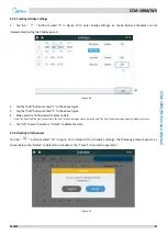
Creating Holiday Settings 

1. 

Tap  the  " 

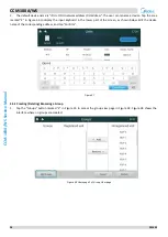
  "  button  marked  "3"  in  Figure  19  to  enter  holiday  settings,  as  shown  below.  Schedules  are  not 

implemented during the holiday period. 


Figure 26 


2. 

Tap the "Add" button marked "1" in the above figure. 

3. 

Tap the "Edit" button marked "2" in the above figure. 

4. 

Slide upward and downward to select a date.   

Note: "By Date" and "By Day" are available. "By Date" means setting by month, date and year; "By Day" means setting by a day in a week of a month. 

5. 

Tap "OK" to save the date or "Delete" to delete the date. 


4.3.3


Deleting All Schedules 

Tap the " 

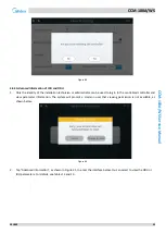
  " button marked "10" in Figure 19 to delete all the schedules settings. The following prompt appears, as 

shown below. Tap "Delete" to delete the schedule or tap "Cancel" to cancel the operation. 


Figure 27 


Summary of Contents for CCM-180A/WS

Page 1: ...Foshan Guangdong China Postal code 528311 Tel 86 757 26338346 Fax 86 757 22390205 cac midea com global midea com Note Product specifications change from time to time as product improvements and develo...

Page 2: ...cations 4 3 Installation Procedure 5 3 1 Mounting the Controller 5 3 2 Centralized Controller Wiring Diagram 7 3 3 Debugging the Centralized Controller 8 4 Getting Started 9 4 1 Home Page Button and D...

Page 3: ...ve atmosphere 1 3 Electrical DANGER RISK OF ELECTROCUTION Turn OFF all power supply before connecting electrical wiring or touching electrical parts Disconnect the power supply for more than 1 minute...

Page 4: ...shock or fire Note Install the wires at least 1 meter away from televisions or radios to prevent interference Depending on the radio waves a distance of 1 meter may not be sufficient WARNING After fi...

Page 5: ...ut 12V DC Manual x1 Cable tie x1 Screw x4 ST3 9 16 Centralized controller x1 2 1 Specifications Table 1 Specifications Adapter Input AC 100 240V 50 60Hz 800mA Output DC 12 0V 2A Centralized controller...

Page 6: ...w of the centralized controller unit mm 3 1 Mounting the Controller 3 1 1 Remove the back cover from the controller using a Phillips head screwdriver See Figure 2 Figure 2 Remove back cover from contr...

Page 7: ...ixed to the positions shown in Figure 4 using cable ties Figure 4 Centralized controller wiring diagram and cable tie fixing hole 3 1 4 Insert the centralized controller into two buckles slantwise at...

Page 8: ...needs to be set for the ODU main board according to the manual Connect the centralized controller to the XY terminal of the communication board of the ODU through the shielded wire using the method sh...

Page 9: ...e pole Connect it to the corresponding wiring terminal on the centralized controller back 3 3 Debugging the Centralized Controller The technician installing the products needs to perform debugging For...

Page 10: ...Service Manual 4 Getting Started 4 1 Home Page Button and Display Description This section includes the descriptions for login page and home page and provides the instructions related to these two pag...

Page 11: ...the USB storage device to provide the software upgrading and error code exporting functions 8 Logout Back to login page 9 Date and Time Display date and time 10 Today s Schedule Display the list of sc...

Page 12: ...e home interface automatically It will then skip the login interface after it is powered on each time 4 1 2 Logout Tap the icon marked 8 in the top left corner of the home page to exit the login inter...

Page 13: ...s are selected Tap the Select All position The tick changes to gray indicating that no IDU is selected 4 2 2 Choosing IDU Group Tap the position marked 2 in Figure 11 to open the drop down menu as sho...

Page 14: ...e list display mode only the status parameters of the IDU can be viewed Table 3 provides the parameter abbreviations and corresponding description IDUs can be selected for operations on in the icon di...

Page 15: ...different operating modes and IDU statuses refer to Table 5 2 Model icon The icon will change according to the model refer to Table 6 The icon may be different from the actual appearance 3 Room Temper...

Page 16: ...con Model Icon Model Low static pressure and middle static pressure L DUCT M DUCT Vertical concealed installation vertical surface mounting FS High static pressure H DUCT Four way Cassette Purifier FA...

Page 17: ...2 7 Setting Mode Directly tap the area marked 3 in Figure 16 Select one of the five modes Note The centralized controller automatically identifies if the connected system is in auto mode If yes the au...

Page 18: ...Control page 4 2 10 Setting Auto Swing Tap the icon marked 2 in Figure 17 to set the Vertical automatic swing switch 4 2 11 Lock Control Panel Tap the Advanced option marked 3 in Figure 17 to access t...

Page 19: ...button Disable changing mode Unlock button Disable the lock Cooling Set Temp Limit 17 C 30 C 62 F 86 F button Set the lowest temperature limitation 17 C 30 C 62 F 86 F Unlock button Disable the lock...

Page 20: ...upper left of a date means there is a set schedule for that day 2 Edit the schedule for the current day Display and edit the schedule list information for the current day 3 Holiday settings Add or ed...

Page 21: ...ap the add schedule button marked 4 in Figure 19 to enter the interface as shown in Figure 20 Figure 20 Page for adding a schedule 2 Tap the position marked 1 in Figure 20 to display the input keyboar...

Page 22: ...rked 3 in Figure 20 tap the drop down menu next to the repeat pattern Select Everyday a work day or customize a pattern Note The command is executed every day in the selected date range Work days are...

Page 23: ...Then set the scheduled operating mode temperature and fan speed as shown below Tap the Save button to save the settings or the Cancel button to cancel the settings Figure 25 7 Tap the Save button in t...

Page 24: ...ton marked 2 in the above figure 4 Slide upward and downward to select a date Note By Date and By Day are available By Date means setting by month date and year By Day means setting by a day in a week...

Page 25: ...permissions Figure 28 Homepage 1 of the Report page 1 Tap the drop down list in the area marked 1 in Figure 28 and select the group or all the devices to be viewed Figure 29 2 Tap the area marked 2 in...

Page 26: ...there is a historical fault record in the system after the start date and end date are selected the interface shown in Figure 31 will be displayed Figure 31 Homepage 2 of the Report page Figure 32 Fa...

Page 27: ...be exported to the mobile device in csv format The fault data content includes the address date time model and error code as shown in the above figure to facilitate queries The screen will display the...

Page 28: ...up view Query group devices and edit groups 4 5 1 Auto Searches and Naming Devices 1 Tap the Units button as shown in Figure 35 to enter the interface as shown in Figure 36 Figure 36 Device installati...

Page 29: ...o display the input keyboard in the lower part of the screen as shown below Edit the device name of the corresponding address and tap Confirm Figure 37 4 5 2 Creating Deleting Renaming a Group 1 Tap t...

Page 30: ...Select a group and tap Rename as shown in Figure 39 to edit the selected group name 5 Tap the Save button as shown in the lower part of Figure 39 to save the edited information 4 5 3 Adding Deleting a...

Page 31: ...t Settings Edits the user account Software Upgrade Updates the centralized controller software version Power Restriction Mode ODU power restriction settings refer to the section about energy saving DI...

Page 32: ...ects timed locking when there is no operation on the centralized controller Backlight Brightness Selects backlight brightness Language Chinese and English Temperature Unit Switches between C and F Eme...

Page 33: ...to actual conditions Note The daylight saving time is disabled by default 4 6 2 Emergency Shut Down ON OFF If an emergency occurs tap the button marked 2 in Figure 42 to enable emergency shutdown The...

Page 34: ...dministrator can be used to log in to the centralized controller and view parameter information The system will prompt a common user that viewing permission is not available as shown below Figure 45 2...

Page 35: ...ture 7 IA Inverter compressor A current 8 IB Inverter compressor B current 9 Fan A DC fan A A1 speed 10 Fan B DC fan B B1 speed 11 EXV A Electronic expansion valve A opening 12 EXV B Electronic expans...

Page 36: ...ompressor 2 frequency 32 Version Program version No Table 13 Advanced Information Parameters of 2nd generation IDU No Parameter Description 1 Address IDU and ODU communication address 2 Group Wired co...

Page 37: ...ed controller 2 Tap Account Settings as shown in Figure 41 to enter the interface as shown in Figure 47 Figure 47 Homepage of Account Settings page 3 Tap the Add User button in the lower right corner...

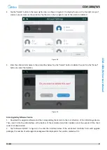
Page 38: ...e the user Tap the Cancel button to cancel the deletion Figure 50 4 6 6 Upgrading Software Version 1 Download the upgrade software and the corresponding check code to the root directory of the USB sto...

Page 39: ...below which displays the upgrade packages e g MD 00 XX Figure 52 4 Select the version to be upgraded in the upgrade list A small blue tick is displayed when the version is selected After you tap Yes...

Page 40: ...DU Only the installation technician and administrator can perform the operation For the options description see Table 14 Figure 54 4 6 8 Setting Silent Mode The setting is valid for new generation ODU...

Page 41: ...ions description see Table 14 Figure 57 Table 14 Set DIP table and centralized controller options of new generation ODU Definition ODU parameter Centralized Controller Options Power Restriction Mode n...

Page 42: ...n speed and compressor frequency 4 9 Super silent mode 2 limit max fan speed and compressor frequency 5 A Super silent mode 3 limit max fan speed and compressor frequency 6 B Super silent mode 4 limit...

Page 43: ...nger cooling refrigerant inlet temperature sensor T6A error F6 Electronic expansion valve EEV connection error xH0 Communication error between the main control chip and inverter driver chip H2 Number...

Page 44: ...representing compressor system B 2 For some error codes a manual restart is required before the system can resume normal operations 3 Once the EEV is connected properly a manual restart is required b...

Page 45: ...hunde Foshan Guangdong China Postal code 528311 Tel 86 757 26338346 Fax 86 757 22390205 cac midea com global midea com Note Product specifications change from time to time as product improvements and...

Reviews: