background image

Pr

oduct Featur

es

 Page 31 

1.6.3  Outdoor Fan Control

For on-off models, outdoor units just have one single fan 
speed. The operation of outdoor fan is consistent with the 
operation of compressor, except the following situations.

•  High temperature protection of evaporator
•  Defrosting
•  Current protection

1.6.4  Defrosting mode 

•  The unit enters defrosting mode according to the 

temperature difference between T2 and T1, as well as 
the compressor runtime.

•  In defrosting mode, the compressor continues to run, 

the indoor and outdoor motor will cease operation, 
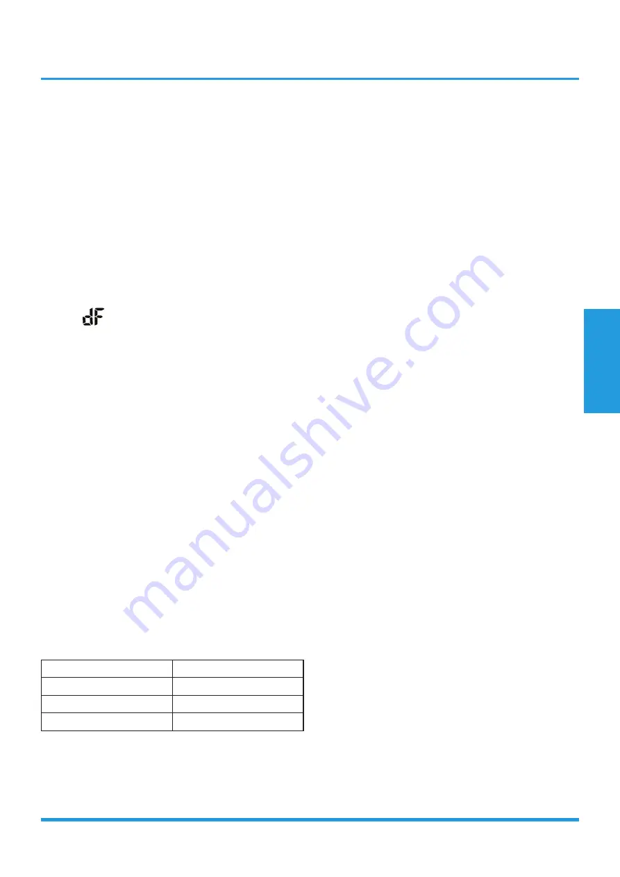
the defrost light of the indoor unit will turn on, and 

the “

” symbol is displayed.

•  If any one of the following conditions is satisfied, 

defrosting ends and the machine switches to normal 
heating mode:

•  Compressor current is over than I

defrost 

and lasts for 

7s

•  The defrosting time has reached the setting value.
•   T2≥2°C(3.6°F) after entering defrosting mode for 3 

minutes.

•  After entering defrosting mode for 2 minutes, 

check the value of T2. The minimum temperature 
of T2 is marked as T2min. If T2-T2min≥2°C(3.6°F) 
during the following 4 minutes, AC will exit 
defrosting mode(if T2≤-15°C(5°F),considers it as 
-15°C(5°F)).

1.6.5  Evaporator Temperature Protection

When the evaporator temperature exceeds a preset 
protection value, the compressor stops.

1.7  Auto-mode

•  This mode can be selected with the remote controller

.

•  In auto mode, the machine selects cooling, heating, or 

fan-only mode on the basis of 

T (

T =T1-Ts).

∆T

Running mode

∆T>2

Cooling

-3

≤∆T≤2

Fan-only

∆T<-3

Heating*

Heating*: In auto mode, cooling only models run the fan

•  AC will run in auto mode in the below cases:

•  Pressing the forced auto button.
•  If AC is off, it will run in auto mode when the timer 

on function is active.

•  After setting the mode, AC will run in auto mode if 

the compressor keeps not running for certain time.

1.8  Drying mode

•  The compressor is cycled running with 10 minutes 

on and then 5 minutes off. The indoor fan will keep 
running at low speed.

•  In drying mode, if room temperature is lower than 

10

°C

, the compressor will stop and not resume until 

room temperature exceeds 13

°C

.

•  The evaporator anti-freezing protection is the same as 

that in cooling mode.

1.9  Forced operation function

•  Forced cooling mode:

The compressor and outdoor fan continue to run and 
the indoor fan runs at low speed. After running for 30 
minutes, the AC will switch to auto mode with a preset 
temperature of 24°C.

•  Forced auto mode:

Forced auto mode operates the same as normal auto mode 
with a preset temperature of 24°C.

•  The unit exits forced operation when it receives the 

following signals:

•  Switch on 
•  Switch off 
•  Timer on 
•  Timer off 
•  Changes in:

•  mode
•  fan speed
•  sleeping mode

1.10  Auto-Restart function

•  The indoor unit has an auto-restart module that 

allows the unit to restart automatically. The module 
automatically stores the current settings (not including 
the swing setting) and, in the case of a sudden power 
failure, will restore those setting automatically within 3 
minutes after power returns.

•  If the unit was in forced cooling mode, it will run in 

this mode for 30 minutes and turn to auto mode with 

Summary of Contents for Forest MOAA31-12CN1-NB8

Page 1: ...FOREST R410A ONOFF CONTROL TM_AF_R410A_ONOFF_SA_NA_2008 TECHNICAL MANUAL ...

Page 2: ...ght Difference 8 Noise Criterion Curves 9 Electrical Characteristics 2 Product Features 28 1 Operation Modes and Functions 2 Remote Controller Functions 3 Installation 34 1 Installation Overview 2 Location Selection 3 Indoor Unit Installation 4 Outdoor Unit Installation 5 Refrigerant Pipe Installation 6 Vacuum Drying and Leakage Checking 7 Additional Refrigerant Charge 8 Electrical and Gas Leak Ch...

Page 3: ...cations 5 3 Dimensional Drawings 7 4 Electrical Wiring Diagrams 11 5 Refrigerant Cycle Diagrams 15 6 Capacity Tables 16 7 Capacity Correction Factor for Height Difference 22 8 Noise Criterion Curves 23 9 Electrical Characteristics 27 Specifications ...

Page 4: ...ine the specific indoor and outdoor unit model number of your purchased equipment Outdoor Unit Model Indoor Unit Model Capacity Btu h Power Supply MOAA31 12CN1 NB8 MSAFB 12CRN1 NB8 12k 1Φ 220 230V 60Hz MOBA32 18CN1 NB8 MSAFC 18CRN1 NB8 18k MOCA30 24CN1 NB8W MSAFD 24CRN1 NB8W 24k ...

Page 5: ...20 4 10L YKFG 28 4 6 5 YKFG 45 4 13 Input W 47 4 58 5 89 0 Insulation class E E B IP rating IPX0 IPX0 IPX0 Capacitor uF 1 5 1 5 3 Capacitor class P2 P2 P2 Speed Hi Mi Lo r min 1150 950 800 1180 1000 800 1200 1000 900 Indoor coil Number of rows 2 0 2 0 2 0 Tube pitch a x row pitch b mm 19 5x11 6 21x13 37 21x13 37 Fin spacing mm 1 2 1 2 1 3 Fin type code Hydrophilic aluminum Hydrophilic aluminum Hyd...

Page 6: ...Gross weight Kg 23 7 25 6 33 4 35 8 42 3 45 3 Refrigerant Type R410A R410A R410A Charged quantity Kg 0 46 0 56 0 91 Design pressure MPa 4 2 1 5 4 2 1 5 4 2 1 5 Refrigerant piping Liquid side Gas side mm inch Φ6 35 Φ9 52 1 4 3 8 Φ6 35 Φ12 7 1 4 1 2 Φ9 52 Φ15 9 3 8 5 8 Max refrigerant pipe length m 20 25 25 Max difference in level m 8 10 10 Connection wiring 1 5x3Core 2 5x3Core 1 0x4Core Plug type 1...

Page 7: ...Specifications Page 7 3 Dimensional Drawings 3 1 Indoor Unit W H D Capacity W mm D mm H mm 12k 805 194 285 18k 957 213 302 24k 1040 220 327 ...

Page 8: ...Specifications Page 8 3 2 Outdoor Unit 12k ...

Page 9: ...Specifications Page 9 18k ...

Page 10: ...Specifications Page 10 24k ...

Page 11: ...s 4 1 Indoor unit Abbreviation Paraphrase Y G Yellow Green Conductor ION Positive and Negative Ion Generator CAP Capacitor PLASMA Electronic Dust Collector L LIVE N NEUTRAL T1 Indoor Room Temperature T2 Coil Temperature of Indoor Heat Exchanger 12k 18k ...

Page 12: ...Specifications Page 12 24k ...

Page 13: ...Specifications Page 13 4 2 Outdoor Unit Abbreviation Paraphrase 4 WAY Gas Valve Assembly 4 WAY VALVE AC FAN Alternating Current FAN DC FAN Direct Current FAN COMP Compressor 12k ...

Page 14: ...Specifications Page 14 18k 24k ...

Page 15: ...y Btu h Pipe Size Diameter ø mm inch Piping length m ft Elevation m ft Additional Refrigerant Gas Liquid Rated Max Rated Max 12k 9 52 3 8 6 35 1 4 5 16 4 20 65 6 0 8 26 2 15g m 0 16oz ft 18k 12 7 1 2 6 35 1 4 25 82 0 10 32 8 24k 15 9 5 8 9 52 3 8 25 82 0 10 32 8 30g m 0 32oz ft ...

Page 16: ... 96 2 96 2 96 3 19 3 19 3 19 3 19 S T 0 75 0 85 0 94 1 00 0 59 0 68 0 77 0 86 0 52 0 61 0 70 0 79 0 35 0 44 0 52 0 60 PI 1 47 1 47 1 47 1 47 1 48 1 48 1 48 1 48 1 48 1 48 1 48 1 48 1 49 1 49 1 49 1 49 482 15 TC 3 64 3 64 3 67 3 70 3 85 3 85 3 85 3 85 3 96 3 96 3 96 3 96 4 25 4 25 4 25 4 25 S T 0 73 0 82 0 90 0 99 0 58 0 67 0 75 0 84 0 52 0 60 0 68 0 76 0 36 0 44 0 51 0 59 PI 0 90 0 90 0 90 0 90 0 ...

Page 17: ...04 1 04 1 04 1 04 30 TC 3 32 3 34 3 37 3 40 3 55 3 55 3 55 3 57 3 63 3 63 3 63 3 63 3 92 3 92 3 92 3 92 S T 0 80 0 92 1 00 1 00 0 62 0 73 0 84 0 95 0 53 0 64 0 75 0 86 0 34 0 44 0 54 0 65 PI 1 14 1 14 1 14 1 14 1 14 1 14 1 14 1 14 1 15 1 15 1 15 1 15 1 15 1 15 1 15 1 15 35 TC 3 14 3 17 3 20 3 23 3 37 3 37 3 37 3 40 3 46 3 46 3 52 3 46 3 75 3 75 3 75 3 75 S T 0 82 0 94 1 00 1 00 0 63 0 74 0 86 0 98...

Page 18: ... 71 4 71 4 71 4 71 S T 0 72 0 80 0 89 0 97 0 58 0 66 0 74 0 82 0 51 0 59 0 67 0 75 0 36 0 44 0 51 0 58 PI 2 19 2 19 2 19 2 19 2 20 2 20 2 20 2 20 2 21 2 21 2 21 2 21 2 23 2 23 2 23 2 23 669 15 TC 5 42 5 42 5 42 5 48 5 74 5 74 5 74 5 74 5 91 5 91 5 91 5 91 6 33 6 33 6 33 6 33 S T 0 71 0 80 0 88 0 96 0 58 0 66 0 73 0 81 0 51 0 59 0 67 0 74 0 37 0 44 0 51 0 58 PI 1 33 1 33 1 33 1 33 1 34 1 34 1 34 1 ...

Page 19: ...56 1 56 1 56 1 56 30 TC 4 99 4 99 5 05 5 10 5 30 5 30 5 30 5 36 5 45 5 45 5 45 5 45 5 88 5 88 5 88 5 88 S T 0 76 0 87 0 97 1 00 0 60 0 70 0 80 0 89 0 52 0 62 0 71 0 81 0 35 0 44 0 53 0 62 PI 1 70 1 70 1 70 1 70 1 71 1 71 1 71 1 71 1 71 1 71 1 71 1 71 1 72 1 72 1 72 1 72 35 TC 4 73 4 79 4 85 4 90 5 05 5 05 5 05 5 10 5 19 5 19 5 28 5 19 5 59 5 59 5 59 5 59 S T 0 78 0 88 0 98 1 00 0 61 0 71 0 81 0 91...

Page 20: ... 29 6 29 6 29 6 29 S T 0 73 0 81 0 90 0 98 0 58 0 66 0 75 0 83 0 51 0 59 0 68 0 76 0 36 0 44 0 51 0 59 PI 2 94 2 94 2 94 2 94 2 95 2 95 2 95 2 95 2 96 2 96 2 96 2 96 2 98 2 98 2 98 2 98 850 15 TC 7 23 7 23 7 23 7 29 7 66 7 66 7 66 7 66 7 89 7 89 7 89 7 89 8 46 8 46 8 46 8 46 S T 0 71 0 79 0 87 0 94 0 57 0 65 0 72 0 80 0 51 0 59 0 66 0 73 0 37 0 44 0 50 0 57 PI 1 79 1 79 1 79 1 79 1 78 1 78 1 78 1 ...

Page 21: ... 08 2 08 2 08 2 08 30 TC 6 63 6 63 6 69 6 75 7 06 7 06 7 06 7 12 7 29 7 29 7 29 7 29 7 84 7 84 7 84 7 84 S T 0 76 0 87 0 97 1 00 0 60 0 70 0 80 0 90 0 52 0 62 0 72 0 81 0 35 0 44 0 53 0 62 PI 2 27 2 27 2 27 2 27 2 28 2 28 2 28 2 28 2 28 2 28 2 28 2 28 2 29 2 29 2 29 2 29 35 TC 6 32 6 37 6 43 6 49 6 72 6 72 6 72 6 78 6 92 6 92 7 03 6 92 7 46 7 46 7 46 7 46 S T 0 78 0 89 0 99 1 00 0 61 0 71 0 82 0 9...

Page 22: ...6 0 931 0 910 Capacity Btu h 18k Pipe Length m Cooling 5 10 15 25 Height difference H m Indoor Upper than Outdoor 10 0 960 0 934 0 884 5 0 995 0 969 0 944 0 893 0 1 000 0 974 0 949 0 897 Outdoor Upper than Indoor 5 1 000 0 974 0 949 0 897 10 0 974 0 949 0 897 Capacity Btu h 24k Pipe Length m Cooling 5 10 15 25 Height difference H m Indoor Upper than Outdoor 10 0 960 0 934 0 884 5 0 995 0 969 0 944...

Page 23: ...he unit Data is valid at free field condition Data is valid at nominal operation condition Reference acoustic pressure OdB 20µPa Sound level will vary depending on a range of factors such as theconstruction acousticabsorptioncoefficient ofparticular room in which the equipment is installed The operating conditions are assumed to be standard ...

Page 24: ...Specifications Page 24 12k 18k 24k ...

Page 25: ... is valid at free field condition Data is valid at nominal operation condition Reference acoustic pressure OdB 20µPa Sound level will vary depending on arrange off actors such as the construction acoustic absorption coefficient of particular room in which the equipment is installed The operating conditions are assumed to be standard 12k 18k ...

Page 26: ...C 60 NC 50 NC 40 NC 30 0 10 20 30 40 50 60 70 80 63 125 250 500 1000 2000 4000 8000 Octave Band Sound Pressure Level dB 0dB 0 0002μbar Band Center Frequency Hz Cooling NC 70 NC 60 NC 50 NC 40 NC 30 24k 0 10 20 30 40 50 60 70 80 63 125 250 500 1000 2000 4000 8000 Octave Band Sound Pressure Level dB 0dB 0 0002μbar Band Center Frequency Hz Cooling NC 70 NC 60 NC 50 NC 40 NC 30 ...

Page 27: ... 12k 1 60 220 230 min 198 max 253 7 125 9 10 28 5 5 55 1 0 021 0 288 18k 10 5 11 9 15 41 9 8 05 1 0 048 0 45 24k 14 25 17 25 58 0 10 55 1 0 063 0 6 Notes MCA Minimum Circuit Amperes A TOCA Total Over current Amps A MFA Maximum Fuse Amperes A MSC Maximum Starting Current RLA Rated Load Amperes A OFM Outdoor Fan Motor FLA Full Load Amperes A ...

Page 28: ...oling Mode 30 1 6 Heating Mode Heat Pump Units 30 1 7 Auto mode 31 1 8 Drying Mode 31 1 9 Forced Operation Function 31 1 10 Auto Restart Function 31 1 11 Refrigerant Leakage Detection 32 1 12 Self clean Optional 32 1 13 Follow me Optional 32 2 Remote Controller Functions 32 2 1 Infrared Wireless Remote Controller 32 Product Features ...

Page 29: ...hen the unit is on timer or When TIMER is on WiFi control available on select units only Temperature value Temperature 3s Activation of Timer ON Fresh Swing Turbo or Silent 3s Cancellation of Timer OFF Fresh Swing Turbo or Silent Defrost Warming in heating mode Self clean available on select units only Heating in room temperature under 8 C set temperature gradually illuminates to in one second int...

Page 30: ...or by compressor overload This is measured using the coil temperature of evaporator T2 when the compressor is in operation 1 4 Fan Mode When fan mode is activated The outdoor fan and compressor are stopped Temperature control is disabled and no temperature setting is displayed The indoor fan speed can be set to high medium low or auto The louver operations are identical to those in cooling mode Au...

Page 31: ...T1 Ts T Running mode T 2 Cooling 3 T 2 Fan only T 3 Heating Heating In auto mode cooling only models run the fan AC will run in auto mode in the below cases Pressing the forced auto button If AC is off it will run in auto mode when the timer on function is active After setting the mode AC will run in auto mode if the compressor keeps not running for certain time 1 8 Drying mode The compressor is c...

Page 32: ...function is active Once active the remote control will send a signal every 3 minutes with no beeps The unit automatically sets the temperature according to the measurements from the remote control The unit will only change modes if the information from the remote control makes it necessary not from the unit s temperature setting If the unit does not receive a signal for 7 minutes or you press Foll...

Page 33: ...ng Each press will increase the time setting in 30 minutes increments up to 10 hours then at 1 hour increments up to 24 hours To cancel the Auto on time setting just press the button until the time setting is 0 0 11 SLEEP Button Press this button to go into the Energy Saving operation mode Press it again to cancel This function is only can be used on COOL HEAT and AUTO mode and maintain the most c...

Page 34: ...ation Selection 37 3 Indoor Unit Installation 39 4 Outdoor Unit Installation 44 5 Refrigerant Pipe Installation 45 6 Vacuum Drying and Leakage Checking 47 7 Additional Refrigerant Charge 48 8 Electrical and Gas Leak Checks 48 9 Test Operation 49 Installation ...

Page 35: ...ating models only Drain joint Owner s manual Installation manual p m i f q J q v m b o l l j f o l k a f q f l k b o l ï å É ê ë j å ì ä l ë á ë m ä ì ë p É ê á É ë ä ä j ç Ç É ä k ì ã Ä É ê ë 1 Remote controller manual AIR CONDI TIONER REMOTE CONTROL LER MANUAL 1 Small Filter Need to be installed on the back of main air filter by the authorized technician while installing the machine 1 2 dependin...

Page 36: ...ation Page 36 1 Installation Overview Installation Order Select Installation Location Attach Mounting Plate Drill Wall Hole Determine Wall Hole Position 1 2 3 4 12cm 4 75in 2 3m 90 55in 12cm 4 75in 15cm 5 9in ...

Page 37: ...Installation Page 37 Mount Indoor Unit STEP 8 Connect Piping Connect Wiring Prepare Refrigerant piping 5 6 7 8 9 W rap Piping and Cable not applicable for some locations in the US ...

Page 38: ... minimum distance between the outdoor unit and walls described in the installation guide does not apply to airtight rooms Be sure to keep the unit unobstructed in at least two of the three directions M N P M N P 30 cm 11 8 from back wall 60 cm 23 6 on right 60 cm 23 6 abov e 30 cm 11 8 on left 200 cm 78 in front 2 4 Rows of series installation The relations between H A and L are as follows L A L H...

Page 39: ...e 6 Relative distances between screw holes Correct orientation of Mounting Plate For Forest series 228 5mm 8 99in 241mm 9 48in 183 6mm 7 2in 123 6mm 4 86in 805mm 31 7in 398mm 15 98in Left rear wall hole 65mm 2 5in Right rear wall hole 65mm 2 5in Indoor unit outline 39mm 1 5in 39mm 1 5in 285mm 11 2in 47 1mm 1 85in 47 1mm 1 85in 45mm 1 7in 117 5mm 4 62in 12k Models Left rear wall hole 65mm 2 5in Rig...

Page 40: ...iping is already embedded in the wall proceed directly to the Connect Drain Hose step If there is no embedded piping connect the indoor unit s refrigerant piping to the connective piping that will join the indoor and outdoor units Refer to the Refrigerant Piping Connection section of this manual for detailed instructions NOTE Refrigerant piping can exit the indoor unit from four different angles L...

Page 41: ...all the unit until the safety issue is properly resolved 4 Power voltage should be within 90 110 of rated voltage Insufficient power supply can cause malfunction electrical shock or fire 5 If connecting power to fixed wiring install a surge protector and main power switch with a capacity of 1 5 times the maximum current of the unit 6 If connecting power to fixed wiring a switch or circuit breaker ...

Page 42: ...ew the cable clamp down tightly 9 Replace the wire cover on the front of the unit and the plastic panel on the back NOTE Choose the right cable size The size of the power supply cable signal cable fuse and switch needed is determined by the maximum current of the unit The maximum current is indicated on the nameplate located on the side panel of the unit Refer to this nameplate to choose the right...

Page 43: ... to the left and right hand sides of the unit The unit should not jiggle or shift 6 Using even pressure push down on the bottom half of the unit Keep pushing down until the unit snaps onto the hooks along the bottom of the mounting plate 7 Again check that the unit is firmly mounted by applying slight pressure to the left and the right hand sides of the unit 3 8 2 If refrigerant piping is already ...

Page 44: ...arthquake or strong wind 4 4 Install drain joint Heat pump units require a drain joint Before bolting the outdoor unit in place you must install the drain joint at the bottom of the unit Note that there are two different types of drain joints depending on the type of outdoor unit If the drain joint comes with a rubber seal see Fig A do the following 1 Fit the rubber seal on the end of the drain jo...

Page 45: ...aps If the indoor unit is installed higher than the outdoor unit If oil flows back into the outdoor unit s compressor this might cause liquid compression or deterioration of oil return Oil traps in the rising gas piping can prevent this An oil trap should be installed every 10m 32 8ft of vertical suction line riser The indoor unit is installed higher than the outdoor unit If the outdoor unit is in...

Page 46: ... by end cover or adhesive tape to avoid duct or exog enous impurity come into the pipe 7 Drill holes if the pipes need to pass the wall 8 According to the field condition to bend the pipes so that it can pass the wall smoothly 9 Bind and wrap the wire together with the insulated pipe if necessary 10 Set the wall conduit 11 Set the supporter for the pipe 12 Locate the pipe and fix it by supporter F...

Page 47: ...hours of drying check whether there is leakage source 4 Leakage test After the vacuum degree reaches 755mmHg stop vacuum drying and keep the pressure for 1 hour If the indicator of vacuum gauge does not go up it is qualified If going up it indicates that there is moisture or leak source 6 3 2 Special vacuum drying The special vacuum drying method shall be adopted when 1 Finding moisture during flu...

Page 48: ...t leakage at the connec tion joint part Using gas leakage detector or soap water to detect 8 Electrical and Gas Leak Checks 8 1 Electrical Safety Checks After installation confirm that all electrical wiring is installed in accordance with local and national regulations and according to the Installation Manual 8 1 1 Before test run Check Grounding Work Measure grounding resistance by visual detecti...

Page 49: ...s are solidly installed All pipe connection points do not leak Outdoor 2 Outdoor 2 Water drains properly from drain hose All piping is properly insulated Unit performs COOL function properly Unit performs HEAT function properly Indoor unit louvers rotate properly Indoor unit responds to remote controller 5 After the Test Run is successfully completed and you confirm that all checks points in List ...

Reviews: