background image

  M thermal Mono

202008                                                                                                                                                                                                                    65

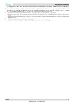
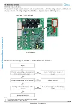
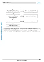
main PCB (labeled 10 in Figure 4-2.1). Domestic hot water tank temperature sensor connection is port CN13 on hydronic system main PCB (labeled 13 in 
Figure 4-2.1).   

3. Set  a  multi-meter  to  buzzer  mode  and  test  any  two  terminals  of  sensor.  If  the  resistance  is  too  low,  the  buzzer  sounds,  which  means  the  sensor has 

short-circuited. If the  resistance  is not consistent  with  the sensor s resistance characteristics table, the sensor  has  failed. Refer to  Part  2, 1  Layout of 
Functional Components  and to Table 5-5.1 or 5-5.2 in Part 5, 5.1 

4.


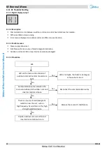
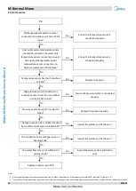
High pressure switch connection is port CN31 on the outdoor unit refrigerant system main PCB (labeled 21 in Figure 4-2.2). 
Measure the resistance among the three terminals of the pressure sensor. If the resistance is of the order of mega Ohms or infinite, the pressure sensor 
has failed. 
High pressure side blockage causes discharge temperature to be higher than normal, discharge pressure to be higher than normal and suction pressure to 
be lower than normal. 

5.


Check air side heat exchanger, fan and air outlets for dirt/blockages. 

6.


Check the water side heat exchanger, water piping, circulator pumps and water flow switch for dirt/blockages. 


Midea CAC Confidential

Summary of Contents for M thermal A Mono Series

Page 1: ...M thermal A Series Mono 18 30kW Commercial Air Conditioners R32 Service Manual Midea CAC Confidential ...

Page 2: ...M thermal Mono 202008 1 CONTENTS CONTENTS Part 1 General Information 3 Part 2 Component Layout and Refrigerant Circuits 5 Part 3 Control 11 Part 4 Diagnosis and Troubleshooting 25 Midea CAC Confidential ...
Page 3: ...M thermal Mono 2 202008 Midea M thermal Mono Service Manual Midea CAC Confidential ...
Page 4: ...M thermal Mono 202008 3 Part 1 General Information Part 1 General Information 1 Unit Capacities and External Appearance 4 Midea CAC Confidential ...

Page 5: ...nit Capacities and External Appearance 1 1 Unit Capacities Table 1 1 1 Capacity range Capacity 18kW 22kW 26kW 30kW Model MHC V18W D2RN8 MHC V22W D2RN8 MHC V26W D2RN8 MHC V30W D2RN8 1 2 External Appearance Table 1 1 2 Appearance 18 22 26 30kW Midea CAC Confidential ...

Page 6: ...202008 5 Part 2 Component Layout and Refrigerant Circuits Part 2 Components Layout and Refrigerant Circuits 1 Layout of Functional Components 6 2 Piping Diagrams 7 3 Refrigerant Flow Diagrams 9 Midea CAC Confidential ...
Page 7: ...otor Gas liquid separator DC inverter compressor Electric control box 4 way valve Pressure sensor Electronic expansion valve High pressure switch Low pressure switch Water pump Safety valve Manometer Figure 2 1 2 MHC V18 22 26 30 W D2RN8 side view Expansion vessel Accumulator One way valve Air purge valve Water flow switch Water side heat exchanger Midea CAC Confidential ...
Page 8: ...lectromagnetic valve 4 4 Way Valve 18 Capillary 5 Outdoor temperature sensor 19 Water Inlet temp sensor 6 Air side heat exchanger 20 Y shape filter Accessories 7 Air side heat exchanger refrigerant outlet temperature sensor cooling 21 Water outlet temp sensor 8 Filter 22 Manometer 9 Electronic expansion valve 23 Safety valve 10 Accumulator 24 Circulating pump 11 Refrigerant temperature sensor liqu...

Page 9: ...on as a condenser 4 High and low pressure switches Regulate refrigerant system pressure When refrigerant system pressure rises above the upper limit or falls below the lower limit the high or low pressure switches turn off stopping the compressor 5 Air purge valve Automatically removes air from the water circuit 6 Safety valve Prevents excessive water pressure by opening at 43 5 psi 3 bar and disc...

Page 10: ... Pressure sensor Filter Electronic expansion valve Filter High pressure switch Low pressure switch Air side heat exchanger Accumulator 4 way valve High temperature high pressure gas High temperature high pressure liquid Low temperature low pressure Single way electromagnetic valve Capillary 3 Refrigerant Flow Diagrams Heating and domestic hot water operation Figure 2 3 1 Refrigerant flow during he...

Page 11: ...M thermal Mono 10 202008 Midea M thermal Mono Service Manual Midea CAC Confidential ...
Page 12: ...ntrol Part 3 Control 1 Stop Operation 12 2 Standby Control 12 3 Startup Control 13 4 Normal Operation Control 14 5 Protection Control 16 6 Special Control 19 7 Roles of Temperature Sensors in Control Functions 22 Midea CAC Confidential ...
Page 13: ...ent refrigerant from mixing with compressor oil when the compressors are stopped The crankcase heater is controlled according to outdoor ambient temperature and the compressor on off state When the outdoor ambient temperature is above 8 C or the compressor is running the crankcase heater is off when the outdoor ambient temperature is at or below 8 C and either the compressor has been stopped for m...

Page 14: ... to startup Once the 60 second stage is complete the program proceeds to the subsequent stages in a step by step fashion and exits when the target rotation speed has been reached 3 3 Startup Control for Heating and Domestic Hot Water Operation Table 3 3 1 Component control during startup in heating and domestic hot water modes Component Wiring diagram label 18 22 26 30kW Control functions and stat...

Page 15: ...mbient temperature and compressor speed Electronic expansion valve EEV1 Controlled according to discharge temperature discharge superheat suction superheat and compressor speed Four way valve ST Off 4 2 Compressor Output Control The compressor rotation speed is controlled according to the load requirement Before compressor startup the M thermal Mono outdoor unit determines the compressor target sp...

Page 16: ...pen When the outdoor unit is power on The EXV first closes fully then moves to the standby position 304 steps After compressor runs for 60 second EXV is controlled according to ambient temperature After a further 180s EXV is controlled according to different modes When the outdoor unit is in standby The EXV is at position 304 steps When the outdoor unit stops The EXV is fully closed firstly then m...

Page 17: ... 1 High Pressure Protection Control This control protects the refrigerant system from abnormally high pressure and protects the compressor from transient spikes in pressure Figure 3 5 1 High pressure protection control Notes 1 Pc Discharge pressure When the discharge pressure rises above 4 2MPa the system displays P1 protection and the unit stops running When the discharge pressure drops below 3 2...

Page 18: ...ps running When the discharge temperature is higher than suction temperature the compressor enters re start control 5 4 Compressor Current Protection Control This control protects the compressor from abnormally high currents Figure 3 5 5 Compressor current protection control When the compressor current rises above Currentmax the system displays P3 protection and the unit stops running When the com...

Page 19: ...fan speed is less than 150rpm for more than 20 seconds When DC fan motor protection control occurs the system displays the H6 error code and the unit stops running After 3 minutes the unit restarts automatically When H6 protection occurs 10 times in 120 minutes the HH error is displayed When an HH error occurs a manual system restart is required before the system can resume operation 5 7 Anti free...

Page 20: ...essor stops Mode change command is received Table 3 6 1 Outdoor unit component control during oil return operation in cooling mode Component Wiring diagram label 18 22 26 30kW Control functions and states Inverter compressor COMP Runs at oil return operation rotation speed DC fan motor FAN_UP FAN_DOWN Controlled according to outdoor heat exchanger pipe temperature ambient temperature discharge tem...

Page 21: ...r domestic hot water when DHW priority has been set on the user interface Refer to the M thermal Mono Engineering Data Book Part 3 7 4 DHW MODE SETTING Menu Domestic hot water demand priority can be ended by changing the switch on controller from on to off Table 3 6 4 Component control during fast DHW operation Component Wiring diagram label 18 22 26 30kW Control functions and states Inverter comp...

Page 22: ...l on off of heat pump Once the heat pump stops internal pump stops to save energy and then balance tank provides hot water for space heating In addition balance tank temperature control can meet both space heating and domestic hot water needs at the same time Balance tank can store energy to provide hot water whilst heat pump runs heat mode cooling which can reduce the host selection and the initi...

Page 23: ... exchanger Accumulatror Compressor Low pressure switch Air purge valve Expansion vessel Circulating pump Safety valve Manometer Accumulatror Electronic expansion valve Filter Distributor Air side heat exchanger Pressure sensor High pressure switch 4 way valve Filter Flow switch Y shape filter Distributor Distributor Collector Collector Fan coil units Floor heating loop Radiator Bypass valve Domest...

Page 24: ...prevention control 10 Cooling 8 Water side heat exchanger water outlet temperature sensor Tw_out Heating Compressor output5 and on off control 6 Freeze prevention control 10 Cooling DHW 9 Final water outlet temperature sensor T1 Heating Compressor output control 5 Backup electric heater control DHW priority control 11 Auto mode control Cooling Compressor output5 and on off control 6 Auto mode cont...

Page 25: ...M thermal Mono 24 202008 Midea M thermal Mono Service Manual Midea CAC Confidential ...

Page 26: ... Mono 202008 25 Part 4 Diagnosis and Troubleshooting 1 Outdoor Unit Electric Control Box Layout 26 2 Outdoor Unit PCBs 27 3 Error Code Table 34 4 Troubleshooting 36 5 Appendix to Part 4 89 Midea CAC Confidential ...
Page 27: ...nit Electric Control Box Layout Figure 4 1 1 Electric control box front view Invert module PCB A Main control board of hydraulic module Main control board of unit PCB B Figure 4 1 2 Electric control box side view Filter board PCB C Invert module PCB A Midea CAC Confidential ...

Page 28: ...models also have an inverter module and a filter board The locations of each PCB in the outdoor unit electric control boxes are shown in Figures 4 1 1 to 4 1 7 in Part 4 1 Outdoor Unit Electric Control Box Layout 2 2 PCB Instruction Figure 4 2 1 MHC V18 22 26 30 W D2RN8 hydronic system main PCB 2 3 4 5 6 7 8 9 10 1 30 29 28 27 26 25 11 12 13 14 15 16 17 18 19 20 21 24 31 23 22 22 Midea CAC Confide...

Page 29: ...thermostat cooling mode CL Power port for room thermostat COM 18 CN35 Port for smart grid grid signal photovoltaic signal 19 CN36 Port for remote switch temperature board 20 CN19 Communicate port between indoor unit and outdoor unit 21 CN14 Port for communication with the wired controller 22 CN30 Communicate port between indoor unit and outdoor unit port for communication with the wired controller...

Page 30: ...thermal Mono 202008 29 Figure 4 2 2 MHC V18 22 26 30 W D2RN8 outdoor unit main PCB for refrigerant system 25 26 26 19 18 2 17 14 23 23 1 11 8 9 3 13 22 12 20 16 15 7 21 10 6 5 4 24 Midea CAC Confidential ...
Page 31: ... box control board 9 CN4 Port for communication with PCB C 10 S5 S6 DIP switch 11 CN26 Port for communication with Power Meter 12 CN22 Port for electrical expansion value 13 CN53 Port for fan 310VDC power supply 14 CN21 Power supply port for hydro box control board 15 CN35 Port for other temp sensor 16 CN28 Port for communication XYE 17 CN18 Port for 4 way value 18 CN10 Port for electric heating t...

Page 32: ... Output port for 15V 2 CN8 Port for communication with PCB B 3 W Compressor connection port W 4 U Compressor connection port U 5 V Compressor connection port V 6 Input port P_out for IPM module 7 Input port P_in for IPM module 8 CN23 Input port for high pressure switch 9 CN2 Power for switching power supply 10 L1 Power filtering L1 11 L2 Power filtering L2 12 L3 Power filtering L3 13 PED board 14 ...

Page 33: ...rd Label in Figure 4 2 4 Code Content 1 L3 Power supply L3 2 L2 Power supply L2 3 L1 Power supply L1 4 N Power supply N 5 PE1 Ground wire 6 CN212 Power supply port for DC fan 7 CN30 Power supply port for main control board 8 L1 Power filtering L1 9 L2 Power filtering L2 10 L3 Power filtering L3 11 CN8 Port for communication with PCB B 12 CN214 Power supply for PCB A switching power supply Midea CA...

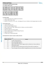
Page 34: ...stem DSP1 Parameters displayed on refrigerant system DSP1 On standby 0 0 Normal operation Leaving water temperature C Running speed of the compressor in rotations per second Error or protection Error or protection code Error or protection code 2 4 Modbus Function Figure 4 2 6 Connection Figure 4 2 7 Wiring Unit Wired controller Modbus Max 16 units Midea CAC Confidential ...
Page 35: ...tion fault between main control board of hydraulic module and main control board PCB B Main control board of unit H1 Communication fault between inverter module PCB A Inverter module and main control board PCB B Main control board of unit H2 The plate exchanger refrigerant outlet liquid pipe temp sensor T2 fault H3 The plate exchanger refrigerant outlet gas pipe temp sensor T2B fault H4 Three time...

Page 36: ...emperature is higher than water outlet in heating mode L0 DC compressor inverter module fault L1 DC bus low voltage protection from inverter module mostly when compressor running L2 DC bus high voltage protection from DC driver L4 MCE fault L5 Zero speed protection L7 Phase sequence fault L8 Compressor frequency variation greater than 15Hz within 1 second protection L9 Actual compressor frequency ...

Page 37: ...ls and in accordance with all applicable legislation all national local and other laws standards codes rules regulations and other legislation that apply in a given situation Power off the outdoor units before connecting or disconnecting any connections or wiring otherwise electric shock which can cause physical injury or death may occur or damage to components may occur Warning Midea CAC Confiden...

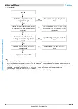
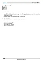
Page 38: ...3 times When an E0 error occurs a manual system restart is required before the system can resume operation M thermal Mono stops running Error code is displayed on hydronic system main PCB and user interface Possible causes 4 2 3 The wire circuit is short connected or open Water flow rate is too low Water flow switch damaged Midea CAC Confidential ...
Page 39: ...irculator pump is not already set to the highest speed increase its speed No Water flow switch is damaged Yes Replace the water flow switch No Internal circulator pump can t work Yes Turn off the power check the wire in the pump Once that is done the pump still work replace the pump No Replace hydronic system main PCB Notes 1 Water flow switch connection is port CN8 on the main PCB for hydronic sy...

Page 40: ...4 3 2 Phase sequence error M thermal Mono stops running Error code is displayed on outdoor unit main PCB and user interface Possible causes 4 3 3 Power supply phases not connected in correct sequence Power supply terminals loose Power supply abnormal Main PCB damaged Midea CAC Confidential ...

Page 41: ...ements If the phase sequence is inverted the compressor will operate inversely If the wiring connection of each outdoor unit is in A B C phase sequence and multiple units are connected the current difference between C phase and A B phases will be very large as the power supply load of each outdoor unit will be on C phase This can easily lead to tripped circuits and terminal wiring burnout Therefor...

Page 42: ...ronic system main PCB and user interface Possible causes 4 4 3 Communication wires between hydronic system and user interface not connected properly Communication wiring X Y E terminals misconnected Loosened wiring within electric control box Interference from high voltage wires or other sources of electromagnetic radiation Damaged main PCB or electric control box communication terminals block Mid...

Page 43: ...o Interference from high voltage 220V or higher wires Yes Ensure the communication wires and high voltage wires are separated No Communication wires are close to a source of electromagnetic radiation such as transformer or strong fluorescent lamp Yes Remove the source of interference or add additional shielding to the communication wires No Replacing electric control box communication terminals bl...

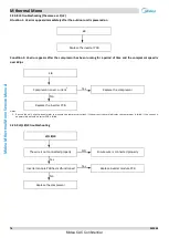
Page 44: ...ater side heat exchanger water inlet temperature sensor error HA indicates a water side heat exchanger water outlet temperature sensor error H5 indicates a room temperature sensor error H9 indicates a circuit 2 water outlet temperature sensor error Eb indicates solar panel temperature sensor error E7 indicates balance tank upper temperature sensor error EC indicates balance tank nether temperature...

Page 45: ... is port CN13 on the hydronic system main PCB labeled 13 in Figure 4 2 1 Circuit 2 water outlet temperature sensor connection is port CN15 on the hydronic system main PCB labeled 14 in Figure 4 2 1 Room temperature sensor connection is port CN11 on the hydronic system main PCB labeled 24 in Figure 4 2 1 Solar panel temperature sensor connection is port CN18 on the hydronic system main PCB labeled ...

Page 46: ... indicates an outdoor ambient temperature sensor error E9 indicates a suction pipe temperature sensor error EA indicates a discharge temperature sensor error M thermal Mono stops running Error code is displayed on outdoor unit main PCB and user interface Possible causes 4 6 3 Temperature sensor not connected properly or has malfunctioned Damaged outdoor unit main PCB Midea CAC Confidential ...

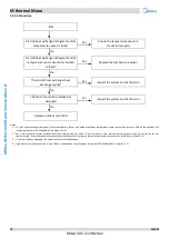
Page 47: ...or unit refrigerant system main PCB labeled 6 in Figure 4 2 2 Discharge pipe temperature sensor connection are port CN8 on the outdoor unit refrigerant system main PCB labeled 5 in Figure 4 2 2 Suction pipe temperature sensor connection are port CN5 on the outdoor unit refrigerant system main PCB labeled 4 in Figure 4 2 2 2 Set a multi meter to buzzer mode and test any two terminals of sensor If t...

Page 48: ...interface Possible causes 4 7 3 Hydronic system main PCB EEPROM is not connected properly Hydronic system main PCB damaged Procedure 4 7 4 EE Hydronic system main PCB EEPROM1 is not connected properly Yes Ensure the EEPROM is connected properly No Replace hydronic system main PCB Notes 1 Hydronic system main PCB EEPROM is designated IC39 on the main PCB for hydronic system labeled 31 in Figure 4 2...

Page 49: ...ronic system main PCB and user interface Possible causes 4 8 3 The DC generatrix voltage is too low Procedure 4 8 4 F1 Power supply is abnormal Yes Provide normal power No LED on the Inverter Modules is lighting Yes Voltage of PN is 380V Yes Check the main board No The input power of inverter module is abnormal Yes The main board is damaged change it No The invert module is damaged change it Midea...

Page 50: ...ce Possible causes 4 9 3 Outdoor unit invert module EEPROM is not connected properly Outdoor unit invert module EEPROM damaged Procedure 4 9 4 HF Outdoor unit invert module EEPROM1 is not connected properly Yes Ensure the EEPROM is connected properly No Replace outdoor unit invert module Notes 1 Outdoor unit invert module EEPROM is designated IC25 on the outdoor unit invert module labeled 14 in Fi...

Page 51: ...n outdoor unit and hydronic system M thermal Mono stops running Error code is displayed on hydronic system main PCB outdoor unit main PCB and user interface Possible causes 4 10 3 Power supply abnormal Transformer malfunction Interference from a source of electromagnetic radiation Outdoor unit main PCB or hydronic system main PCB damaged Midea CAC Confidential ...

Page 52: ...een main control board of outdoor unit and hydraulic module have short circuited disconnected or misconnected Yes Reconnect the communication wires No Replace outdoor unit main PCB and hydronic system main PCB in turn Notes 1 Measure the voltages of transformer input port and out port The input voltage of transformer is 220V AC output voltage of transformer is 13 5V AC If any voltages is abnormal ...

Page 53: ...door unit main PCB or inverter driven module damaged Procedure 4 11 4 H1 LED on the main control board of outdoor unit and inverter module are light Yes LED is not light the board is damaged or have short circuit No Communication wires between the main control board of outdoor unit and inverter module is loose Yes Reconnect the communication wires No There is a source of electromagnetic radiation ...

Page 54: ...s a manual system restart is required before the system can resume operation The cause of HH error should be addressed promptly in order to avoid system damage M thermal Mono stops running Error code is displayed on outdoor unit main PCB and user interface Possible causes 4 12 3 DC fan wire is loosed High wind speed Fan motor blocked or has failed Invert module damaged Main PCB is damaged Midea CA...

Page 55: ...move obstruction or replace the fan motor No Replace outdoor unit main PCB Notes 1 Refer to Figures 4 1 1 to 4 1 2 in M thermal Mono Service Manual and to Part 2 Wiring Diagrams in M thermal Mono Engineering Data Book 2 Measure the voltage between the DC fan motor power supply wires The normal voltage is 15V when the unit is in standby If the voltage is significantly different from 15V the IPM mod...

Page 56: ...nning Error code is displayed on outdoor unit main PCB and user interface Possible causes 4 13 3 Power supply voltage not within 90 110 of rated voltage Outdoor unit main PCB is damaged Procedure 4 13 4 H7 Power supply voltage is not within 90 110 of rated voltage Yes Provide normal power supply No Replace outdoor unit main PCB Midea CAC Confidential ...

Page 57: ... damaged Procedure 4 14 4 H8 No High pressure sensor connection on outdoor unit main PCB is loose Yes Ensure the sensor is connected properly No High pressure sensor has short circuited or failed1 Yes Replace the sensor No Replace outdoor unit main PCB Notes 1 Measure the resistance among the three terminals of the pressure sensor If the resistance is of the order of mega Ohms or infinite the pres...

Page 58: ...essure rises above 0 3MPa P0 is removed and normal operation resumes HP indicates Pe 0 6Mpa occurred 3 times in an hour Error code is displayed on outdoor unit main PCB and user interface Possible causes 4 15 3 Low pressure switch not connected properly or has malfunctioned Insufficient refrigerant Low pressure side blockage Poor evaporator heat exchange in heating mode or DHW mode Insufficient wa...

Page 59: ... PCB Notes 1 To check for insufficient refrigerant An insufficiency of refrigerant causes compressor discharge temperature to be higher than normal discharge and suction pressures to be lower than normal and compressor current to be lower than normal and may cause frosting to occur on the suction pipe These issues disappear once sufficient refrigerant has been charged into the system 2 A low press...

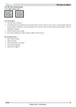
Page 60: ...mal Mono stops running When the discharge pressure falls below 3 2MPa P1 is removed and normal operation resumes Error code is displayed on outdoor unit main PCB and user interface Possible causes 4 16 3 Pressure sensor switch not connected properly or has malfunctioned Excess refrigerant System contains air or nitrogen High pressure side blockage Poor condenser heat exchange Outdoor unit main PCB...

Page 61: ...or main PCB Notes 1 High pressure switch connection is port CN31 on the outdoor unit refrigerant system main PCB labeled 21 in Figure 4 2 2 2 Measure the resistance among the three terminals of the pressure sensor If the resistance is of the order of mega Ohms or infinite the pressure sensor has failed 3 High pressure side blockage causes discharge temperature to be higher than normal discharge pr...

Page 62: ...ystem displays P3 protection and M thermal Mono stops running When the current returns to the normal range P3 is removed and normal operation resumes Error code is displayed on refrigerant system main PCB and user interface Possible causes 4 17 3 Poor condenser heat exchange High pressure side blockage Inverter module damaged Compressor damaged Outdoor unit main PCB damaged Midea CAC Confidential ...

Page 63: ...ng circulator pumps and water flow switch for dirt blockages In cooling mode check air side heat exchanger fan and air outlets for dirt blockages 2 High pressure side blockage causes discharge temperature to be higher than normal discharge pressure to be higher than normal and suction pressure to be lower than normal 3 Set a multi meter to buzzer mode and test any two terminals of P N and U V W of...

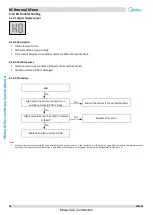
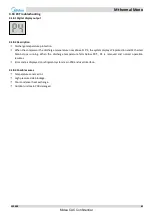
Page 64: ...5 C the system displays P4 protection and M thermal Mono stops running When the discharge temperature falls below 90 C P4 is removed and normal operation resumes Error code is displayed on refrigerant system main PCB and user interface Possible causes 4 18 3 Temperature sensor error High pressure side blockage Poor condenser heat exchange Outdoor unit main PCB damaged Midea CAC Confidential ...

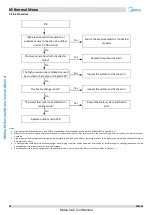
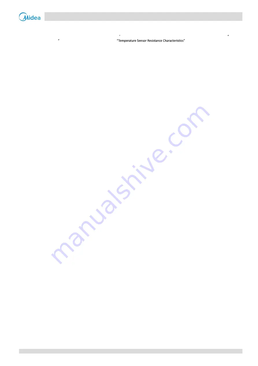
Page 65: ... outdoor unit main PCB is loose4 Yes Ensure the pressure switch is connected properly No Pressure sensor has short circuited or failed5 Yes Replace the pressure sensor No The high pressure side is blocked caused by crushed or bent pipe or blocked EXV4 Yes Inspect the system and fix the error No The condenser heat exchange is poor in heating mode5 Yes Inspect the system and fix the error No The wat...

Page 66: ...ts and to Table 5 5 1 or 5 5 2 in Part 5 5 1 4 High pressure switch connection is port CN31 on the outdoor unit refrigerant system main PCB labeled 21 in Figure 4 2 2 Measure the resistance among the three terminals of the pressure sensor If the resistance is of the order of mega Ohms or infinite the pressure sensor has failed High pressure side blockage causes discharge temperature to be higher t...

Page 67: ... water side heat exchanger water inlet and water outlet temperatures protection M thermal Mono stops running Error code is displayed on hydronic system main PCB and user interface Possible causes 4 19 3 Temperature sensor not connected properly or has malfunctioned Water piping contains air Insufficient water flow Hydronic system main PCB damaged Midea CAC Confidential ...

Page 68: ... vessel3 Yes Inspect the system and fix the error No Replace hydronic system main PCB Notes 1 Water side heat exchanger water inlet temperature sensor and water side heat exchanger water outlet temperature sensor connections are port CN6 on the hydronic system main PCB labeled10 in Figure 4 2 1 2 Set a multi meter to buzzer mode and test any two terminals of sensor If the resistance is too low the...

Page 69: ...on Zero speed protection Excessive compressor frequency variation Actual compressor frequency differs from target frequency High pressure protection Contactor stuck or 908 self checking fail Specific error codes for inverter module protection 4 20 4 Table 4 4 1 Specific error codes Specific error code Content L0 Inverter module protection L1 DC bus low voltage protection L2 DC bus high voltage pro...

Page 70: ...times and stops for 1 second then repeats L8 Compressor frequency variation greater than 15Hz within one second protection L9 Actual compressor frequency differs from target frequency by more than 15Hz protection Flashes 3 times and stops for 1 second then repeats bH Contactor stuck or 908 self checking fail Flashes 5 times and stops for 1 second then repeats P1 High pressure protection Figure 4 4...

Page 71: ...rigerant system main control board for refrigerant system inverter module is port CN36 on refrigerant system main control board for refrigerant system port CN8 on inverter module 2 Measure the resistance between each of U V and W and each of P and N on the inverter module All the resistances should be infinite If any of them are not infinite the inverter module is damaged and should be replaced 3 ...

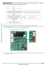
Page 72: ...he main PCB Notes 1 The DC bus wire should run from the N terminal on the inverter module through the current sensor in the direction indicated by the arrow on the current sensor and end at the N terminal of capacitor Refer to Figure 4 4 4 Figure 4 4 4 DC bus wire connection L1L2L3 PIN POUT L1 L2 L3 Pin Pout 2 The normal resistances of the inverter compressor are 0 7 differ from these specificatio...

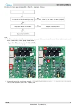
Page 73: ...s 1 Connect the U V W wire from the inverter module to the correct compressor terminals as indicated by the labels on the compressor 2 Measure the voltage between each of W W V V U U and GND when the unit is in standby The normal voltage should be 2 5V 4V and the six voltages should be same otherwise the communication terminal has failed Refer to Figure4 4 5 Figure 4 4 5 Connection port for invert...

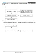
Page 74: ...r No Replace the inverter module2 Notes 1 When replacing an inverter module a layer of thermally conductive silica gel should be painted on the IPM module on the reverse side of the inverter module PCB Refer to Figure 4 4 3 2 Use clip on ammeter to measure the compressor current if the current is normal indicates the inverter module is failed if the current is abnormal indicates the compressor has...

Page 75: ...al 540V DC Situation 1 L1 or L2 error appears immediately after the outdoor unit is powered on L1 L2 P N 15V wire on refrigerant system main PCB is not connected properly1 Yes Ensure P N 15V wire is connected properly No Voltage between N and 15 is abnormal2 Yes Check 15V circuit3 No DC voltage between terminal P and N is abnormal Yes Check power supply three phase bridge rectifier4 No Replace the...

Page 76: ...robe on the DC power output negative terminal terminal 5 and put the black probe onto each of the AC power input terminals terminals 1 2 and 3 in turn The voltage between terminal 5 and each of terminals 1 2 and 3 should be around 0 378V If the voltage is 0 the bridge rectifier has failed Put the red probe on the DC power output positive terminal terminal 4 then put black probe onto each of the AC...

Page 77: ... 60rps L4 Compressor is over current2 Yes Replace the compressor No Replace the inverter PCB Notes 1 Re start the unit use clip on ammeter to measure the compressor current if the current is normal indicates the compressor is failed if the current is abnormal indicates the inverter PCB is failed L5 L8 L9 troubleshooting 4 20 9 L5 L8 L9 The wire is not connected properly NO Ensure wire is connected...

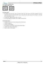
Page 78: ...econds the system displays Pd protection and M thermal Mono stops running When the air side heat exchanger refrigerant outlet temperature returns drops below 55 C Pd is removed and normal operation resumes M thermal Mono stops running Error code is displayed on outdoor unit main PCB and user interface Possible causes 4 21 3 Temperature sensor not connected properly or has malfunctioned Poor conden...

Page 79: ...e outdoor main PCB Notes 1 Air side heat exchanger refrigerant outlet temperature sensor and outdoor ambient temperature sensor connection port are CN9 on the outdoor unit refrigerant system main PCB labeled 6 in Figure 4 2 2 2 Set a multi meter to buzzer mode and test any two terminals of sensor If the resistance is too low the buzzer sounds which means the sensor has short circuited If the resis...

Page 80: ...than outlet temperature in heating mode M thermal Mono stops running Error code is displayed on hydronic system main PCB and user interface Hb indicates PP has displayed 3 times Possible causes 4 22 3 Temperature sensor not connected properly or has malfunctioned 4 way valve is blocked or damaged Hydronic system main PCB damaged Midea CAC Confidential ...

Page 81: ...e heat exchanger water inlet temperature sensor and water side heat exchanger water outlet temperature sensor connections are port CN6 on the hydronic system main PCB labeled 10 in Figure 4 2 1 2 Set a multi meter to buzzer mode and test any two terminals of sensor If the resistance is too low the buzzer sounds which means the sensor has short circuited If the resistance is not consistent with the...

Page 82: ...unning Error code is displayed on hydronic system main PCB and user interface Possible causes 4 23 3 Power supply voltage of the unit is low The space between the units is too narrow for heat exchanger Heat exchanger is dirty or something is block on the surface Fan is not running Water flow rate is low Water outlet temp sensor is loosen or broken Midea CAC Confidential ...

Page 83: ...ow Yes There is air in system or pump head is not enough Release the air and reselect the pump No Water outlet temp sensor1 is loosen or broken Yes Reconnect it or change a new one Notes 1 Water side heat exchanger water inlet temperature sensor and water side heat exchanger water outlet temperature sensor connections are port CN6 on the hydronic system main PCB labeled 10 in Figure 4 2 1 2 Set a ...

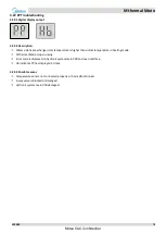
Page 84: ...display output 4 24 1 Description 4 24 2 PED PCB failure M thermal Mono stops running Error code is displayed on hydronic system main PCB and user interface Possible causes 4 24 3 Power supply problem PED board broken IPM module broken Midea CAC Confidential ...

Page 85: ... of power off interval power on again and observe whether it can be recovered Yes Increase the power voltage to the required range No PED1 board broken Yes Replace PED PCB and power on again No IPM module broken Yes Replace IPM module and power on again Notes 1 PED is labeled 13 in Figure 4 2 3 Midea CAC Confidential ...

Page 86: ... system protection Procedure 4 25 4 Pb 1 Outdoor ambient temperature 3 C and water side heat exchanger water outlet temperature water inlet temperature backup electric heater outlet water temperature 5 2 Water side heat exchanger water outlet temperature water inlet temperature backup electric heater outlet water temperature 2 Yes Normal system protection The system will resume automatically1 Note...

Page 87: ... Error code is displayed on hydronic system main PCB outdoor unit main PCB and user interface Possible causes 4 26 3 Temperature collecting plate Optional connection wire is not connected Temperature collecting plate Optional is damaged Procedure 4 26 4 HE Temperature collecting plate connection wire is not connected Yes Check the connection line and joint No Temperature collecting plate is damage...

Page 88: ...n board fuse is damaged Procedure 4 27 4 Hd SW9 DIP switch with wrong settings Yes Check SW9 setting Master unit ON Slave unit OFF No More than two units are connected to the wire controller Yes Make sure there is only one controller connect to master unit No Power on interval between master unit and slave unit is longer than 2min Yes Make sure power on interval between master unit and slave unit ...

Page 89: ...02008 Midea M thermal Mono Service Manual No Address code missing or address code setting duplicate Yes Reset address code by another controller No Main board fuse is damaged Yes Replace main board Midea CAC Confidential ...

Page 90: ...1 496 62 2 181 102 0 574 17 89 353 23 10 971 63 2 102 103 0 558 16 84 278 24 10 473 64 2 026 104 0 542 15 79 521 25 10 65 1 953 105 0 527 14 75 059 26 9 551 66 1 883 13 70 873 27 9 125 67 1 816 12 66 943 28 8 721 68 1 752 11 63 252 29 8 337 69 1 69 10 59 784 30 7 972 70 1 631 9 56 524 31 7 625 71 1 574 8 53 458 32 7 296 72 1 519 7 50 575 33 6 982 73 1 466 6 47 862 34 6 684 74 1 416 5 45 308 35 6 4...

Page 91: ...112 2 630 7 261 4 33 38 89 73 8 643 113 2 559 6 247 8 34 37 30 74 8 358 114 2 489 5 234 9 35 35 78 75 8 084 115 2 422 4 222 8 36 34 32 76 7 820 116 2 357 3 211 4 37 32 94 77 7 566 117 2 294 2 200 7 38 31 62 78 7 321 118 2 233 1 190 5 39 30 36 79 7 086 119 2 174 0 180 9 40 29 15 80 6 859 120 2 117 1 171 9 41 28 00 81 6 641 121 2 061 2 163 3 42 26 90 82 6 430 122 2 007 3 155 2 43 25 86 83 6 228 123 ...

Page 92: ... 2734 19 444 548 21 58 804 61 11 715 101 3 1777 18 419 907 22 56 209 62 11 302 102 3 0853 17 396 779 23 53 742 63 10 906 103 2 9960 16 375 063 24 51 396 64 10 526 104 2 9096 15 354 662 25 49 165 65 10 161 105 2 8262 14 335 492 26 47 043 66 9 8105 13 317 470 27 45 025 67 9 4736 12 300 521 28 43 104 68 9 1498 11 284 576 29 41 276 69 8 8387 10 269 569 30 39 535 70 8 5396 9 255 439 31 37 878 71 8 2520...

Page 93: ... midea com www midea group com Note Product specifications change from time to time as product improvements and developments are released and may vary from those in this document GD MIDEA Heating Ventilating Equipment Co Ltd participates in the ECP programme for LCP HP Check ongoing validity of certificate www eurovent certification com Midea CAC Confidential ...

Reviews: