M thermal Mono
202008 75
3.
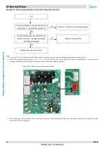
Check the +15V circuit according to corresponding wiring diagram. If IC4/5/6PIN12 on inverter module output voltage is not +15V means the inverter
module is failed. If voltage output of inverter module is +15V means main PCB is failed.
4.
Check the bridge rectifier using one of the following two methods (refer to Figure 4-4.8):
Method 1: measure the resistance between any two of the 5 bridge rectifier terminals. If any of the resistances is close to zero, the bridge rectifier
has failed.
Method 2: dial a multimeter to the diode setting:
-
Put the red probe on the DC power output negative terminal (terminal 5) and put the black probe onto each of the AC power input terminals
(terminals 1, 2 and 3) in turn. The voltage between terminal 5 and each of terminals 1, 2 and 3 should be around 0.378V. If the voltage is 0, the
bridge rectifier has failed.
-
Put the red probe on the DC power output positive terminal (terminal 4), then put black probe onto each of the AC power input terminals
(terminals 1, 2 and 3) in turn. The voltage between terminal 4 and each of terminals 1, 2 and 3 should be infinite. If the voltage is 0, the bridge
rectifier has failed.
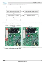
Figure 4-4.8: Bridge rectifier
Three phase AC power input
DC power output
Figure 4-4.7: P N +15V te15V IC4/5/6PIN12
N- IC/4/5 6 PIN13
Schematic diagram
+15V
N
Midea CAC Confidential


