221
8 Electronic function
8.1 Electric Control working environment
8.1.1 input voltage: 175~253V
8.1.2 Input power frequency:50Hz
8.1.3 Ambient
temperature:
-7
°
C~+43
°
C
8.1.4 Indoor fan normal working amp is less than 1A,
8.1.5 Outdoor fan. Normal working amp is less than 1.5A
8.1.6 Four-way valve normal working amp is less than 1A.
8.1.7 Swing motor: DC12V.
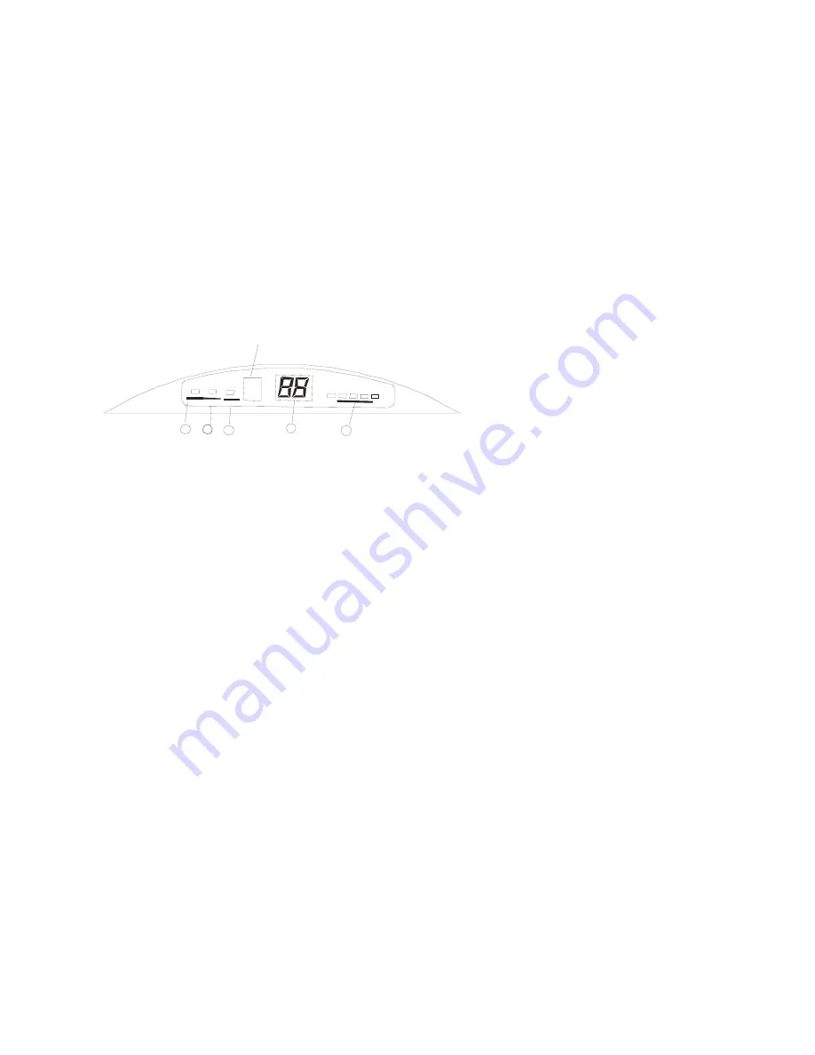
8.2 Display
board
Signal receptor
1
22
3
4
5
8.2.1 AUTO indicator
This indicator illuminates when the air conditioner is in AUTO operation.
8.2.2 TIMER indicator
This indicator illuminates when TIMER is set ON/OFF.
8.2.3 PRE.-DEF. Indicator (For Cooling & Heating models only)
This indicator illuminates when the air conditioner starts defrosting automatically or when
the warm air control feature is activated in heating mode.
8.2.4 TEMPERATURE indicator
a) Usually it displays the temperature settings. When change the setting temperature, this
indicator begins to flash, and stops 20 seconds later.
b) It displays the room temperature when the air conditioner is in FAN only operation.
c) When the unit stops operation, it returns to original factory settings.
d) Displays the malfunction code or protection code.
8.2.5 OXYGEN GENERATOR indicator (Optional)
This indicator appears only when the Oxygen Generatorr is in operation.(Optional)
8.3
Proper symbols and their meanings
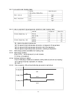
TA: Indoor ambient temperature
TE: Indoor evaporator temperature
TS: Setting temperature through the remote controller
TE1: Anti-cold wind, from Fan Off to Breeze temperature
TE2: Anti-cold wind, from Breeze to Setting Fan Speed temperature
TE3: Anti-cold wind, from Setting Fan Speed to Breeze temperature
TE4: Anti-cold wind, from Breeze to Fan Off temperature
TE5: Evaporator low temperature protection entering temperature
TE6: Evaporator low temperature protection restoring temperature
Summary of Contents for M2OA-18HRN1
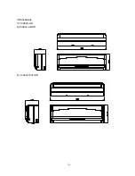
Page 8: ...214 3 Dimensions 3 1 Indoor unit a Indoor unit 9K b Indoor Unit 12K...
Page 9: ...215 3 2 Outdoor unit a Outdoor unit 18K 21K b Outdoor unit 27K 30K...
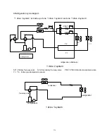
Page 12: ...218 6 Wiring diagram Indoor unit CORONA INDOOR UNIT Outdoor unit FOR 1 DRIVE 2 OUTDOOR UNIT...
Page 13: ...219 FOR 1 DRIVE 3 OUTDOOR UNIT...
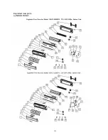
Page 22: ...228 Exploded view parts a INDOOR UNIT...
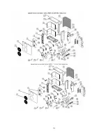
Page 23: ...229 b UNIVERSAL OUTDOOR UNIT...
Page 24: ...230...


