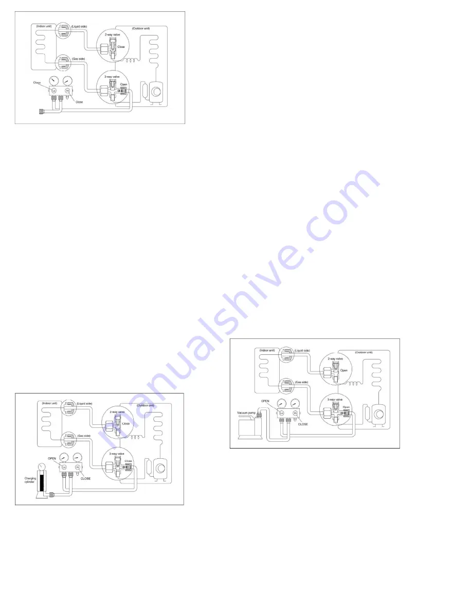
Procedure
1). Confirm that both the 2-way and 3-way valves
are set to the opened position
Remove the valve stem caps and confirm that the
valve stems are in the opened position.
Be sure to use a hexagonal wrench to operate the
valve stems.
2). Connect the charge hose with the push pin of
handle lo to the 3-way valves gas service port.
3). Air purging of the charge hose.
Open the handle Lo valve of the manifold valve
slightly to purge air from the charge hose for 5
seconds and then close it quickly.
4). Set the 2-way valve to the close position.
5). Operate the air conditioner at the cooling cycle
and stop it when the gauge indicates
0.1Mpa(14.5Psi)..
6). Set the 3-way valve to the closed position
immediately
Do this quickly so that the gauge ends up indicating
0.3Mpa(43.5Psi) to 0.5 Mpa(72.5Psi)..
Disconnect the charge set, and tighten the 2-way
and 3-way valve’s stem nuts.
Use a torque wrench to tighten the 3-way valves
service port cap to a torque of 18N.m.
Be sure to check for gas leakage.
2. Air purging by the refrigerant
Procedure:
1). Confirm that both the 2-way and 3-way valves
are set to the closed position.
2). Connect the charge set and a charging cylinder
to the service port of the 3-way valve
Leave the valve on the charging cylinder closed.
3). Air purging.
Open the valves on the charging cylinder and the
charge set. Purge the air by loosening the flare
nut on the 2-way valve approximately 45’ for 3
seconds then closing it for 1 minute; repeat 3
times.
After purging the air, use a torque wrench to tighten
the flare nut on the 2-way valve.
4). Check the gas leakage
Check the flare connections for gas leakage.
5). Discharge the refrigerant.
Close the valve on the charging cylinder and
discharge the refrigerant by loosening the flare
nut on the 2-way valve approximately 45’ until the
gauge indicates 0.3Mpa(43.5Psi) to 0.5
Mpa(72.5Psi)..
6). Disconnect the charge set and the charging
cylinder, and set the 2-way and 3-way valves to
the open position
Be sure to use a hexagonal wrench to operate the
valve stems.
7). Mount the valve stems nuts and the service port
cap
Be sure to use a torque wrench to tighten the
service port cap to a torque 18N.m.
Be sure to check the gas leakage.
6.7 Re-installation while the outdoor unit
need to be repaired
1. Evacuation for
the whole system
Procedure:
1). Confirm that both the 2-way and 3-way valves
are set to the opened position.
2). Connect the vacuum pump to 3-way valve’s
service port.
3). Evacuation for approximately one hour. Confirm
that the compound meter indicates -0.1Mpa
(14.5Psi).
4). Close the valve (Low side) on the charge set,
Summary of Contents for M2OC-18HFN1-M
Page 19: ...8 Wiring Diagrams 8 1 Wiring diagram of 1 drive 2 outdoor M2OC 18HFN1 M M2OD 18HFN1 M...
Page 20: ...PCB board of M2OC 18HFN1 M M2OD 18HFN1 M...
Page 21: ...IPM board of M2OC 18HFN1 M...
Page 22: ...IPM board of M2OD 18HFN1 M...
Page 23: ...8 2 Wiring diagram of 1 drive 3 outdoor M3OD 27HRDN1 M M3OC 30HRFN1 M...
Page 24: ...PCB board of M3OC 30HRFN1 M...
Page 25: ...IPM board of M3OC 30HRFN1 M...
Page 26: ...PCB board of M3OD 27HRDN1 M...
Page 27: ...IPM board of M3OD 27HRDN1 M...
Page 28: ...8 3 Wiring diagram of 1 drive 4 outdoor M4OC 36HRFN1 M...
Page 29: ...PCB board of M4OC 36HRFN1 M...
Page 30: ...IPM board of M4OC 36HRFN1 M...
Page 31: ...PFC board of M4OC 36HRFN1 M...
Page 66: ...IPM for dual tri zone IPM for qua zone P N for dual tri zone...
Page 67: ...P N for qua zone...
Page 68: ...bridge rectifier for dual tri zone bridge rectifier for qua zone...
Page 69: ...Remark Measure the DC voltage between and port The normal value should be 190V 250V...
Page 71: ...Two ports of the inductance Inductance...
Page 72: ......
Page 77: ......
Page 79: ......
Page 81: ......
Page 83: ......
Page 96: ...6 EXV check Disconnect the connectors...
Page 98: ...Red Blue Red Yellow...
Page 99: ...Brown Orange Brown White...
Page 114: ...Screws of front panel Screws of right rear panel Screws of top cover...
Page 128: ......


