33
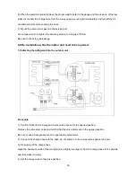
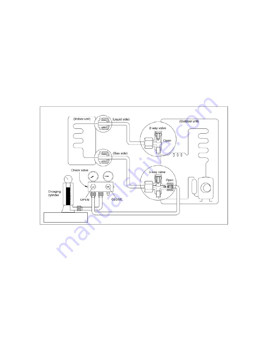
Close the valve on the charging cylinder and discharge the refrigerant by loosening the flare nut on the
2-way valve approximately 45’ until the gauge indicates 0.3 to 0.5 Mpa.
6). Disconnect the charge set and the charging cylinder, and set the 2-way and 3-way valves to the open
position.
Be sure to use a hexagonal wrench to operate the valve stems.
7). Mount the valve stems nuts and the service port cap.
Be sure to use a torque wrench to tighten the service port cap to a torque 18N
·
m.
Be sure to check the gas leakage.
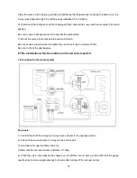
3. Adding the refrigerant if the pipe length >5m
Procedure:
1). Connect the charge hose to the charging cylinder, open the 2-way valve and the 3-way valve.
Connect the charge hose which you disconnected from the vacuum pump to the valve at the bottom of
the cylinder. If the refrigerant is R410A, make the cylinder bottom up to ensure the liquid charge.
2). Purge the air from the charge hose
Open the valve at the bottom of the cylinder and press the check valve on the charge set to purge the
air (be careful of the liquid refrigerant).
3) Put the charging cylinder onto the electronic scale and record the weight.
4) Operate the air conditioner at the cooling mode.
5) Open the valves (Low side) on the charge set and charge the system with liquid refrigerant.
Electronic scale
Summary of Contents for MA9A-24HR-QB4W
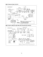
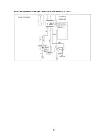
Page 19: ...17 MS9A 18CR QB6...
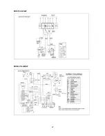
Page 20: ...18 MS9A 18CR PC4W A MS9A 05CR QD0 MS9A 09CR QB6 A MS9A 09CR QB6 MS9A 09CR QC0 MS9A 09CR QC4 A...
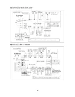
Page 21: ...19 MS9A 12CR QC4 A MS9A 18CR QC0 MS9A 18CR QC2 MS9A 18CR QB8 MS9A 18CR QC4 A MS9A 18CR QC0 A...
Page 22: ...20 MS9A 21HR QB6W MA9A 24HR QB4W MS9A 22CR QC0 MS9A 22CR QB8...
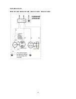
Page 23: ...21 5 2 Outdoor Units MOK2 07C QB6 MOK6 09C QB6 MOA1 12C QB6 MOA2 12C QB6...
Page 24: ...22 MOB 18C QB6...
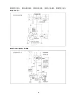
Page 25: ...23 MOK 07H QB6 MOK3 09H QB6 MOB 12H QB6 MOA1 12H QB4 MOA2 12H QB6...
Page 27: ...25 MOB3 18C QB8 MOC2 18C QC0 MOB1 18CP QC0 MOB2 18CP QC0...
Page 28: ...26 MOB 18H QB6...
Page 29: ...27 MOF 18C QC4W MOF4 21H QB6W...

