background image


36 

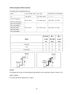
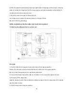
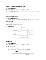
5). Operate the air conditioner at the cooling cycle and stop it when the gauge indicates 0.1MPa. 

6). Set the 3-way valve to the closed position immediately. 

Do this quickly so that the gauge ends up indicating 0.3 to 0.5Mpa. 

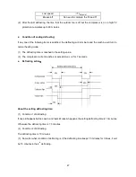
Disconnect the charge set, and tighten the 2-way and 3-way valve’s stem nuts.   

Use a torque wrench to tighten the 3-way valves service port cap to a torque of 18N.m. 

Be sure to check for gas leakage. 

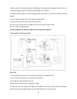
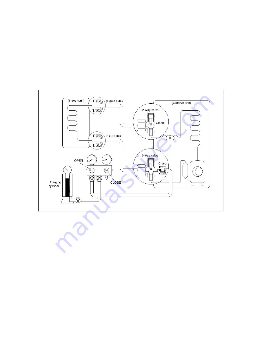
2. Air purging by the refrigerant


Procedure: 

1). Confirm that both the 2-way and 3-way valves are set to the closed position. 

2). Connect the charge set and a charging cylinder to the service port of the 3-way valve. 

Leave the valve on the charging cylinder closed. 

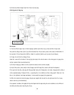
3). Air purging 

Open the valves on the charging cylinder and the charge set. Purge the air by loosening the flare nut on 

the 2-way valve approximately 45’ for 3 seconds then closing it for 1 minute; repeat 3 times. 

After purging the air, use a torque wrench to tighten the flare nut on the 2-way valve. 

4). Check the gas leakage 

Check the flare connections for gas leakage. 

5). Discharge the refrigerant 

Summary of Contents for MA9A-24HR-QB4W

Page 1: ...9ASAP 1301 A SERVICE MANUAL MIDEA AIRCONDITIONER ASIA PACIFIC OCEAN MARKET SPLIT WALL MOUNTED TYPE LUNA ON OFF SERIES...

Page 2: ...6 3 Pipe length and the elevation 30 6 4 Installation for the first time 31 6 5 Adding the refrigerant after running the system for many years 34 6 6 Re installation while the indoor unit need to be r...

Page 3: ...le or repair the product there is risk of fire or electric shock Always ground the product There is risk of fire or electric shock Install the panel and the cover of control box securely There is risk...

Page 4: ...uring operation There is risk of fire or electric shock Do not place anything on the power cable There is risk of fire or electric shock Do not plug or unplug the power supply plug during operation Th...

Page 5: ...ion that water could not enter the product There is risk of fire electric shock or product damage Ventilate the product from time to time when operating it together with a stove etc There is risk of f...

Page 6: ...preserving foods works of art etc It is a consumer air conditioner not a precision refrigerant system There is risk of damage or loss of property Do not block the inlet or outlet of air flow It may ca...

Page 7: ...es of the same type Do not mix old and mew batteries or different types of batteries There is risk of fire or explosion Do not recharge or disassemble the batteries Do not dispose of batteries in a fi...

Page 8: ...OK8 09C QB6 MS9A 09CR QB6 MOK9 09C QB6 MS9A 09CR QC0 MOB1 09C QC0 MS9A 09CR QC4 A MOB1 09C QC4 12k MS9A 12CR QC4 A MOB2 12C QC4 MS9A 12CR QB6 MOA1 12C QB6 MS9A 12CR QB6 MOA2 12C QB6 MS9A 12HR QB4 MOA1...

Page 9: ...7 MS9A 18CR QC0 A MOB1 18CP QC0 MS9A 18CR QC0 MOB2 18CP QC0 21k MS9A 21HR QB6W MOF4 21H QB6W 22k MS9A 22CR QC0 MOF 22C QC0 MS9A 22CR QB8 MOF 22C QB8 24k MA9A 24HR QB4W MOF 24H QB4...

Page 10: ...Filter O Bio Filter O Golden Fin O Killer of Formaldehyde Compressor Crankcase Heater O Self Clean O Follow me O 8 degree heating O Heat compensation O Self diag function Hydrophilic aluminum fin Anti...

Page 11: ...9A 09HR QB6 MS9A 09CR QB6 A 790 265 198 MS9A 09CR QC0 MS9A 09CR QC4 A MS9A 12CR QB6 MS9A 12HR QB4 MS9A 12HR QB6 MS9A 12CR QC4 A 920 292 223 MS9A 18CR QC0 MS9A 18CR QB6 MS9A 18HR QB6 MS9A 18CR PC4W A 9...

Page 12: ...65 MS9A 07CR QB6 MS9A 07HR QB6 MS9A 09CR QB6 MS9A 09HR QB6 MS9A 09CR QB6 A 151 100 45 MS9A 09CR QC0 MS9A 09CR QC4 A MS9A 12CR QB6 MS9A 12HR QB4 MS9A 12HR QB6 MS9A 18CR QC2 118 5 100 45 MS9A 18CR QB8...

Page 13: ...11 Model R mm L mm H mm Dimension of installation hole mm MS9A 12CR QC4 A 186 5 150 45 65 MS9A 18CR QC0 MS9A 18CR QB6 MS9A 18HR QB6 MS9A 18CR PC4W A 120 100 45 H L R...

Page 14: ...m Service space Fence or obstacles Model W D H W1 A B MOK 05CP QD0 685 260 430 742 460 276 MOK2 07C QB6 MOK 07H QB6 MOK8 09C QB6 MOK9 09C QB6 MOK6 09C QB6 MOK3 09H QB6 MOA1 12C QB6 700 240 540 757 458...

Page 15: ...2H QB6 MOB 18C QB6 MOB3 18C QB8 MOB1 18CP QC0 MOB2 18CP QC0 MOB 18H QB6 MOF 18C QC4W 845 320 700 908 560 335 MOF 18C QC2 MOF2 18C QC4 MOF4 21H QB6W MOF 22C QC0 MOF 22C QB8 MOF 24H QB4 MOC2 18C QC0 760...

Page 16: ...14 4 Refrigerant Cycle Diagram For cooling only models INDOOR OUTDOOR LIQUID SIDE GAS SIDE HEAT EXCHANGE EVAPORATOR HEAT EXCHANGE CONDENSER COMPRESSOR CAPILIARY TUBE...

Page 17: ...DOOR OUTDOOR LIQUID SIDE GAS SIDE HEAT EXCHANGE EVAPORATOR HEAT EXCHANGE CONDENSER COMPRESSOR 2 WAY VALVE 3 WAY VALVE CHECK VALVE Heating Model only CAPILIARY TUBE REVERSING VALVE Heating Model only C...

Page 18: ...16 5 Wiring Diagram 5 1 Indoor Units MS9A 07CR QB6 MS9A 09CR QB6 MS9A 12CR QB6 MS9A 07HR QB6 MS9A 09HR QB6 MS9A 12HR QB4 MS9A 12HR QB6 MS9A 18HR QB6...

Page 19: ...17 MS9A 18CR QB6...

Page 20: ...18 MS9A 18CR PC4W A MS9A 05CR QD0 MS9A 09CR QB6 A MS9A 09CR QB6 MS9A 09CR QC0 MS9A 09CR QC4 A...

Page 21: ...19 MS9A 12CR QC4 A MS9A 18CR QC0 MS9A 18CR QC2 MS9A 18CR QB8 MS9A 18CR QC4 A MS9A 18CR QC0 A...

Page 22: ...20 MS9A 21HR QB6W MA9A 24HR QB4W MS9A 22CR QC0 MS9A 22CR QB8...

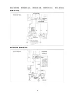
Page 23: ...21 5 2 Outdoor Units MOK2 07C QB6 MOK6 09C QB6 MOA1 12C QB6 MOA2 12C QB6...

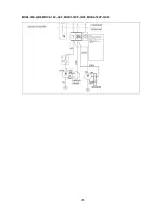
Page 24: ...22 MOB 18C QB6...

Page 25: ...23 MOK 07H QB6 MOK3 09H QB6 MOB 12H QB6 MOA1 12H QB4 MOA2 12H QB6...

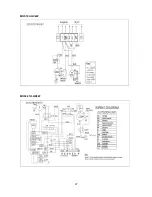
Page 26: ...24 MOK 05CP QD0 MOK8 09C QB6 MOK9 09C QB6 MOB1 09C QC0 MOB1 09C QC4 MOB2 12C QC4 MOF 18C QC2 MOF2 18C QC4...

Page 27: ...25 MOB3 18C QB8 MOC2 18C QC0 MOB1 18CP QC0 MOB2 18CP QC0...

Page 28: ...26 MOB 18H QB6...

Page 29: ...27 MOF 18C QC4W MOF4 21H QB6W...

Page 30: ...28 MOF 22C QC0 MOF 22C QB8 MOF 24H QB4...

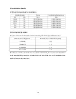
Page 31: ...4 6500 663kgf cm 6700 683kgf cm 6 2 Connecting the cables The power cord of connect should be selected according to the following specifications sheet Rated current of appliance Nominal cross sectiona...

Page 32: ...vacuum pump Pipe length 5 30g m MS9A 18CR PC4W A More than 5m Use vacuum pump Pipe length 5 60g m MS9A 21HR QB6W MS9A 22CR QC0 MS9A 22CR QB8 MA9A 24HR QB4W Model Standard length m Max Elevation B m M...

Page 33: ...t brush to check for leakage of the connecting points of the piping If bubbles come out the pipes have leakage 1 Air purging with vacuum pump 1 Completely tighten the flare nuts of the indoor and outd...

Page 34: ...indicator is a little higher than the atmosphere pressure Then remove the charge hose from the 3 way valve 8 Fully open the 2 way valve and 3 way valve and securely tighten the cap of the 3 way valve...

Page 35: ...rant if the pipe length 5m Procedure 1 Connect the charge hose to the charging cylinder open the 2 way valve and the 3 way valve Connect the charge hose which you disconnected from the vacuum pump to...

Page 36: ...nnect the charge hose to the 3 way service port open the 2 way valve and the 3 way valve Connect the charge hose to the valve at the bottom of the cylinder If the refrigerant is R410A make the cylinde...

Page 37: ...e the indoor unit need to be repaired 1 Collecting the refrigerant into the outdoor unit Procedure 1 Confirm that both the 2 way and 3 way valves are set to the opened position Remove the valve stem c...

Page 38: ...y the refrigerant Procedure 1 Confirm that both the 2 way and 3 way valves are set to the closed position 2 Connect the charge set and a charging cylinder to the service port of the 3 way valve Leave...

Page 39: ...to use a torque wrench to tighten the service port cap to a torque 18N m Be sure to check the gas leakage 6 7 Re installation while the outdoor unit need to be repaired 1 Evacuation for the whole syst...

Page 40: ...Put the charging cylinder onto the electronic scale and record the weight 4 Open the valves Low side on the charge set and charge the system with liquid refrigerant If the system cannot be charge wit...

Page 41: ...39 6 Mounted the valve stem caps and the service port Use torque wrench to tighten the service port cap to a torque of 18N m Be sure to check for gas leakage...

Page 42: ...the unit to function abnormally 2 Room relative humidity less than 80 If the air conditioner operates in excess of this figure the surface of the air conditioner may attract condensation Please set t...

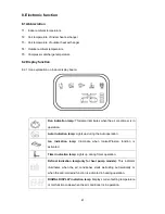
Page 43: ...ir conditioner is in operation Auto indication lamp Lights up during the Auto operation Ion indication lamp Illuminate when Ionizer Plasma function is activated Timer indication lamp Lights up during...

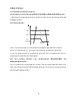
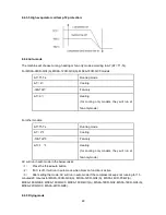
Page 44: ...tdoor fan will shut off B zone The current exceeds I5min for 5 minutes the compressor and outdoor fan will shut off C zone The current exceeds IFAN the outdoor fan will shut off if AC is in heating mo...

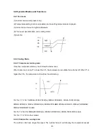
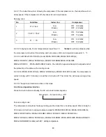
Page 45: ...the below rules When indoor room temp T1 is lower than Tn the compressor and outdoor fan will shut off When T1 is higher than Tm the compressor and outdoor fan will start up Tm Ts 1 Tn Ts 1 for MS9A 1...

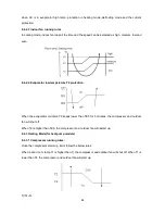
Page 46: ...on When the evaporator coil temp T2 keeps lower than TE5 for 5 minutes the compressor and outdoor fan will shut off When T2 is higher than TE6 the compressor and outdoor fan will restart up 8 4 3 Heat...

Page 47: ...compressor is on And when the compressor is off the indoor fan will run at low speed and the louver will locate at the anti cold wind angle Anti cold wind function When evaporator coil temp T2 is gett...

Page 48: ...to 90 minutes Condition of defrosting stop If any one of the following items is satisfied the defrosting will terminate and the machine will turn to normal heating mode 1 T3 rises to be higher than TC...

Page 49: ...mode 1 The defrosting time is reached to the setting value 2 The compressor current reaches or exceeds IDEFROST for 7 seconds Defrosting action About the setting defrosting time 1 Condition 1 of defro...

Page 50: ...s Running mode T 2 Cooling 1 T 2 Fan only T 1 Heating for cooling only models they will run at fan only mode AC will run in auto mode in the below cases 1 Press the forced auto button 2 If AC is off i...

Page 51: ...A 22CR QC0 MA9A 24HR QB4W models the indoor fan speed will keep at low speed and all the protection is the same as the cooling mode 8 4 5 4 For MS9A 09CR QC4 A MS9A 12CR QC4 A MS9A 18CR QC0 models the...

Page 52: ...e AC is off now it will not start up firstly after setting the timer off function And when reaching the setting time the timer LED will be off and the AC running mode has not been changed 8 4 7 7 The...

Page 53: ...ation setting not including Swing function automatically after 3 minutes when power returns If the memorization condition is forced cooling mode the unit will run in cooling mode for 30 minutes and tu...

Page 54: ...QB6 Display LED STATUS E1 EEPROM error E2 Zero crossing signal detection error E3 Indoor fan speed has been out of control E4 Over current protection occurs 4 times E5 Open circuit or short circuit of...

Page 55: ...oor fan speed has been out of control O The T1 or T2 sensor is open circuit or short circuit X Over current protection occurs 4 times except MS9A 09CR QC4 A MS9A 12CR QC4 A MS9A 18CR QC0 O EEPROM erro...

Page 56: ...ace the indoor main PCB Shut off the power supply and turn it on 5 seconds later Is it still displaying the error code EEPROM a read only memory whose contents can be erased and reprogrammed using a p...

Page 57: ...ly Find out the cause and have it solved For example check whether the fan is blocked or the bearing is broken Check the wires of fan motor Are all the connections good No Yes No Correct the connectio...

Page 58: ...ess than 100V 208 240V power supply or 50V 115V power supply the PCB must has problems and need to be replaced 9 2 4 Open circuit or short circuit of temperature sensors diagnosis and solution Check t...

Page 59: ...re too high Does the outdoor unit has bad air circulation Yes No Check if the outdoor fan can run properly No Correct the connection of fan motor or replace the fan motor Yes Yes Check if the compress...

Page 60: ...ll displaying after several minutes No Yes Change the outdoor main PCB Power on Is the error extinguished Check all the wirings between indoor and outdoor indoor main PCB and outdoor main PCB followin...

Page 61: ...r Compressor discharge temp T5 sensor Measure the resistance value of each winding by using the multi meter Table1 Some frequently used R T data for T1 T2 T3 and T4 sensor Temperature 5 10 15 20 25 30...

Reviews: