background image

MCAC-ATSM-2014-09                                                                                          R410A tropical air-cooled scroll chiller unit 60Hz 

137 

WEEKLY TIMER SETTING 


NOTE: 

In operating, press the key "CANCEL", to turn back to the previous step or the normal display interface. 

WEEKLY TIMER QUERY 


Select week

Set Period 1 start hour

ADDRESS/-

A

OK

Y

OK

A

or

or

Set Period 1 start minute

ADDRESS/-

OK

A

or

Y

Y

OK

Y

OK

Y

OK

Y

Y

OK

TIMER SET

Set Period 1 end hour

ADDRESS/-

A

or

Set Period 1 end minute

ADDRESS/-

A

or

Set Period 1 mode

ADDRESS/-

A

or

Set Period 1 temperature

ADDRESS/-

A

Set Timer Period 2

or

ADDRESS/-

Set Period 2 start hour

ADDRESS/-

OK

A

or

Set Period 2 start minute

ADDRESS/-

OK

A

or

Y

Y

OK

Y

OK

Y

OK

Y

Y

OK

Set Period 2 end hour

ADDRESS/-

A

or

Set Period 2 end minute

ADDRESS/-

A

or

Set Period 2 mode

ADDRESS/-

A

or

Set Period 2 temperature

ADDRESS/-

A

or

Select week

ADDRESS/-

A

or

Set Timer Period 2

OK

Select query week

Select query Period 1

or Period 2

ADDRESS/-

A

OK

Y

OK

A

or

or

Select query start
time or end time

ADDRESS/-

OK

A

or

Y

Y

To normal display

ADDRESS/-

TIMER QUERY

Summary of Contents for MGBT-F120W/PN1

Page 1: ... Features 4 3 Specification 8 4 Dimension 14 5 Refrigeration system drawing 22 6 Piping diagram 24 7 Wiring diagram 28 8 Electric characteristics 36 9 Capacity tables 38 10 Exploded view 46 11 Trouble shooting 61 12 Installation 76 13 Commissioning 101 14 Maintenance 102 15 Control system 106 Appendix 167 ...

Page 2: ...e 16 480 KJRM 120D BMK E 3 MGBT F60W PN1 380V 3Ph 60Hz Shell and tube 16 960 KJRM 120D BMK E 4 MGBT F120W PN1 380V 3Ph 60Hz Shell and tube 8 960 KJRM 120D BMK E 5 MGBT F180W PN1 380V 3Ph 60Hz Shell and tube 5 900 KJRM 120D BMK E Refrigerant type N1 R410A Omit for R22 Power Supply P 380V 60Hz 3Ph D 220V 60Hz 3Ph Outdoor Unit Rated cooling capacity kW The special function code D Digital scroll F Fix...

Page 3: ...R410A tropical air cooled scroll chiller unit 60Hz MCAC ATSM 2014 09 4 1 3 External appearance 60kW 120kW 180kW 30kW ...

Page 4: ... for design and installation The unit adopts modular design which can make more units to connect together The units can be combined freely meanwhile every separate module can be operated as main unit also each module can be a slave unit with modules combination more convenient for design and installation 4 The maximum combination of the system consists of 1 main unit and 15 slave units for 30kW 60...

Page 5: ...t fails all the units will stop If one slave unit fails this unit will stop but the others will keep running When the master unit fails any of the slave one can be set as the master unit by manual setting When unit is under protection If master unit s protection occurs this unit will stop but the others will keep running If slave unit s protection occurs this unit will stop but the others will kee...

Page 6: ...Heating 10 C 24 C 22 C 50 C Chilled outlet water temperature can be adjusted by wired controller according to customer s demand 15 C Ambient temperature range 10 C 5 C 0 C 5 C 10 C 15 C 20 C 25 C 30 C 35 C 40 C 45 C 50 C Cooling range 10 C 52 C Heating range 10 C 24 C Water outlet temperature range 5 C 17 C 50 C 5 C 17 C Heating range Cooling range 40 C 22 C 0 C 40 C 50 C Cooling range 0 C 17 C He...

Page 7: ...E TF7 522 Quantity Pieces 2 1 1 Capacity Btu h 58000 50400 58000 Input kW 5 48 4 71 5 48 Rate load current RLA A 10 1 9 6 10 1 Locked rotor Amp LRA A 94 65 6 94 Refrigerant oil ml 1685 1242 1685 Refrigerant Type R410A R410A Refrigerant control EXV EXV Weight lb 6 834 2 6 834 2 Condenser Air side Air side heat exchanger type Fin coil Fin coil Quantity of fan motor Pieces 1 1 Air flow volume 10 3 m ...

Page 8: ...perature difference protection 9 Compressor discharge temperature protection 10 Water flow cut off protection 11 Sensor malfunction protection 12 Low temperature protection of shell and tube heat exchanger Noise level dB A 67 Operation water temperature Cooling 0 17 Less than 5 must add antifreeze Heating 22 50 Ambient temperature Cooling 10 52 Heating 10 21 Note Please refer to the water flow vol...

Page 9: ...RLA A 21 4 21 4 Locked rotor Amp LRA A 124 124 Refrigerant oil ml 3300 3300 Refrigerant Type R410A R410A Refrigerant control EXV capillary EXV capillary Weight lb 14 33 2 14 33 4 Condenser Air side Air side heat exchanger type Fin coil Fin coil Quantity of fan motor Pieces 2 4 Air flow volume 10 3 m 3 h 24 48 Fan motor model YS650 8C YS650 8C Fan motor rated current A 2 1 2 2 1 4 Fan motor input k...

Page 10: ...ressor discharge temperature protection 10 Water flow cut off protection 11 Sensor malfunction protection 12 Low temperature protection of shell and tube heat exchanger Noise level dB A 67 70 Operation water temperature Cooling 0 17 Less than 5 must add antifreeze Heating 22 50 Ambient temperature Cooling 10 52 Heating 10 21 Note Please refer to the water flow volume in the above table strictly to...

Page 11: ... 9 9 Rate load current RLA A 21 4 Locked rotor Amp LRA A 124 Refrigerant oil ml 3300 Refrigerant Type R410A Refrigerant control EXV capillary Weight lb 14 33 6 Condenser Air side Air side heat exchanger type Fin coil Quantity of fan motor Pieces 6 Air flow volume 10 3 m 3 h 72 Fan motor model YS650 8C Fan motor rated current A 2 1 6 Fan motor input kW 1 03 6 Evaporator Water side Water side heat e...

Page 12: ...ompressor discharge temperature protection 21 Water flow cut off protection 22 Sensor malfunction protection 12 Low temperature protection of shell and tube heat exchanger Noise level dB A 74 Operation water temperature Cooling 0 17 Less than 5 must add antifreeze Heating 22 50 Ambient temperature Cooling 10 52 Heating 10 24 Note Please refer to the water flow volume in the above table strictly to...

Page 13: ... tropical air cooled scroll chiller unit 60Hz MCAC ATSM 2014 09 14 4 Dimension 30kW module Model Unit A B C D E F MGCT F30W PN1 MGCT D30W PN1 mm 1514 841 1865 115 315 172 inch 59 6 33 11 73 43 4 53 12 4 6 77 ...

Page 14: ...MCAC ATSM 2014 09 R410A tropical air cooled scroll chiller unit 60Hz 15 No Name 1 Top cover 2 Air outlet 3 Air inlet 4 Water outlet 5 Water inlet 6 Electric control box ...

Page 15: ...chiller unit 60Hz MCAC ATSM 2014 09 16 60kW module Front view Top view Model Unit A B C D E F G H I J K MGBT F60W PN1 mm 2000 900 1880 350 1420 225 1500 506 530 930 450 inch 78 74 35 4 74 13 78 55 91 8 86 59 06 19 92 20 87 36 61 17 72 ...

Page 16: ...MCAC ATSM 2014 09 R410A tropical air cooled scroll chiller unit 60Hz 17 No Name 1 Top cover 2 Air outlet 3 Air inlet 4 Water outlet 5 Compressor 6 Electric control box 7 Water inlet ...

Page 17: ...ll chiller unit 60Hz MCAC ATSM 2014 09 18 120kW module Front view Side view Top view Anchor hole Model Unit A B C D E F G H MGBT F120W PN1 mm 2000 1685 2080 355 1420 506 1550 1586 inch 78 74 66 34 81 89 13 98 55 91 19 92 61 02 62 44 ...

Page 18: ...CAC ATSM 2014 09 R410A tropical air cooled scroll chiller unit 60Hz 19 No Name 1 Top cover 2 Condenser 3 Compressor 4 Evaporator 5 Electric control box air inlet 6 Water outlet 7 Water inlet 8 Compressor ...

Page 19: ...ical air cooled scroll chiller unit 60Hz MCAC ATSM 2014 09 20 180kW module Model unit A B C D E F G H MGBT F180W PN1 mm 2850 2000 2110 3470 2156 506 1888 2388 inch 112 2 78 74 83 07 136 61 84 88 19 92 74 33 94 02 ...

Page 20: ...MCAC ATSM 2014 09 R410A tropical air cooled scroll chiller unit 60Hz 21 No Name 1 Top cover 2 Compressor 3 Evaporator 4 Water outlet 5 Electric control box 6 Water inlet 7 Condenser ...

Page 21: ...inder A Low pressure cylinder B 4 way valve A 4 way valve B Condenser Evaporator Double pipe heat exchanger Fan Water outlet Water inlet EXV EXV 5 2 60kW module refrigeration system sketch drawing Each module has two compressors with one separate unit one shell and tube evaporator for two refrigerant systems Dry type evaporator Condenser Water flow direction Compressor B low pressure cylinder B 4 ...

Page 22: ...cylinder B 4 Way valve A Fan A EXV Capillary EXV 2 1 2 Unit 2 Capillary Fan B 4 Way valve B Compressor A low pressure cylinder A Unit 1 5 4 180kW module refrigeration system sketch drawing Each module has six compressors with three separate units one shell and tube evaporator for six refrigerant systems Dry type evaporator Condenser Water flow direction Compressor B low pressure cylinder B 4 Way v...

Page 23: ... 6 1 30kW module water pipeline sketch drawing The table below describes the symbols Symbol Symbol explanation Symbol Symbol explanation Stop valve Y shaped filter Pressure gauge Thermometer Water flow switch Circulating pump Gate valve Check valve Flexible joint Automatic discharge valve ...

Page 24: ...l explanation Symbol Symbol explanation Stop valve Y shaped filter Pressure gauge Thermometer Water flow switch Circulating pump Gate valve Check valve Flexible joint Automatic discharge valve Main unit Expansion tank Water replenishing Dirt discharge valve Differential pressure by pass valve Drain valve Two way valve Three way valve Terminal Auxiliary electric heater ...

Page 25: ...W module water pipeline sketch drawing The table below describes the symbols Symbol Symbol explanation Symbol Symbol explanation Stop valve Y shaped filter Pressure gauge Thermometer Water flow switch Circulating pump Gate valve Check valve Flexible joint Automatic discharge valve ...

Page 26: ...W module water pipeline sketch drawing The table below describes the symbols Symbol Symbol explanation Symbol Symbol explanation Stop valve Y shaped filter Pressure gauge Thermometer Water flow switch Circulating pump Gate valve Check valve Flexible joint Automatic discharge valve ...

Page 27: ...L 11 WA Y TE RMI NA L XT2 B LUE BLUE GRAY YE LL OW BLACK G RA Y BLACK RE D BR OW N RE D RE D GRAY YE LLO W R ED B L U E B L U E Y EL L O W B LU E BLUE MAIN BOARD CURRENT BOARD O RA N G E BLUE P U R P LE R E D PWM PRESSURE RELIF VALVE BLUE Y G M IDD LE WIR E J OIN T M IDD LE W IRE J OIN T M ID DL E W IR E JO IN T S V A 4 VALVE A 4 W AY T E R MI N A L X T 1 P OWE R I N S W3 S1 16 WAY DAIL SWITCH FUN...

Page 28: ...MCAC ATSM 2014 09 R410A tropical air cooled scroll chiller unit 60Hz 29 60kW module ...

Page 29: ...R410A tropical air cooled scroll chiller unit 60Hz MCAC ATSM 2014 09 30 120kW module ...

Page 30: ...MCAC ATSM 2014 09 R410A tropical air cooled scroll chiller unit 60Hz 31 180kW module ...

Page 31: ...R410A tropical air cooled scroll chiller unit 60Hz MCAC ATSM 2014 09 32 7 2 Networking communication schematic 30kW module ...

Page 32: ...MCAC ATSM 2014 09 R410A tropical air cooled scroll chiller unit 60Hz 33 60kW module ...

Page 33: ...R410A tropical air cooled scroll chiller unit 60Hz MCAC ATSM 2014 09 34 120kW module ...

Page 34: ...MCAC ATSM 2014 09 R410A tropical air cooled scroll chiller unit 60Hz 35 180kW module ...

Page 35: ... 1 2 0 85 4 MGCT D30W PN1 60 3 380 342 418 28 5 36 65 6 94 9 6 10 1 0 85 4 MGBT F60W PN1 60 3 380 342 418 55 6 70 124 2 21 4 2 1 03 2 2 1 2 MGBT F120W PN1 60 3 380 342 418 222 4 260 124 4 21 4 4 1 03 4 2 1 4 MGBT F180W PN1 60 3 380 342 418 180 300 124 6 21 4 6 1 03 6 2 1 6 Remark TOCA Total Over current Amps A MFA Max Fuse Amps A LRA Locked Rotor Amps A RLA Rated Load Amps A OFM Outdoor Fan Motor ...

Page 36: ......

Page 37: ... 9 70 30 00 10 00 28 17 10 50 25 97 11 03 23 43 11 58 8 00 37 04 9 40 34 78 9 69 32 72 9 99 30 84 10 30 28 99 10 82 26 76 11 36 24 16 11 92 9 00 38 09 9 49 35 73 9 79 33 58 10 09 31 62 10 40 29 75 10 92 27 49 11 47 24 85 12 04 10 00 39 53 9 63 37 05 9 93 34 79 10 24 32 73 10 56 30 83 11 08 28 52 11 64 25 81 12 22 11 00 40 63 9 73 38 05 10 03 35 69 10 34 33 54 10 66 31 63 11 19 29 29 11 75 26 54 12...

Page 38: ... 37 34 9 78 42 79 10 56 43 00 18 22 6 52 22 86 7 40 26 98 8 23 30 08 8 94 32 80 9 41 36 54 9 98 41 81 10 77 44 00 17 86 6 65 22 44 7 55 26 53 8 39 29 61 9 12 32 32 9 60 35 94 10 18 41 04 10 99 45 00 17 60 6 78 22 14 7 71 26 21 8 57 29 28 9 31 32 00 9 80 35 52 10 39 40 49 11 22 46 00 17 26 6 85 21 74 7 79 25 76 8 65 28 81 9 40 31 52 9 90 34 92 10 49 39 74 11 33 47 00 16 75 6 99 21 12 7 94 25 06 8 8...

Page 39: ...70 56 34 20 69 51 95 21 72 46 85 22 81 8 00 74 09 18 52 69 57 19 09 65 44 19 68 61 68 20 29 57 98 21 31 53 51 22 37 48 32 23 49 9 00 76 18 18 70 71 46 19 28 67 16 19 87 63 24 20 49 59 51 21 51 54 99 22 59 49 71 23 72 10 00 79 06 18 98 74 10 19 57 69 58 20 17 65 45 20 80 61 66 21 84 57 03 22 93 51 61 24 07 11 00 81 27 19 17 76 09 19 76 71 38 20 37 67 09 21 00 63 27 22 05 58 58 23 15 53 08 24 31 12 ...

Page 40: ... 85 86 93 21 44 43 00 37 00 13 23 46 42 15 03 54 81 16 70 61 10 18 16 66 63 19 11 74 23 20 26 84 92 21 88 44 00 36 28 13 50 45 58 15 34 53 88 17 04 60 14 18 53 65 65 19 50 73 00 20 67 83 37 22 33 45 00 35 76 13 77 44 98 15 65 53 23 17 39 59 48 18 91 65 00 19 90 72 15 21 09 82 25 22 78 46 00 35 06 13 91 44 15 15 81 52 32 17 57 58 52 19 09 64 03 20 10 70 94 21 30 80 73 23 01 47 00 34 02 14 19 42 90 ...

Page 41: ...89 43 44 93 71 45 61 8 00 148 17 37 04 139 13 38 18 130 88 39 36 123 36 40 58 115 96 42 61 107 03 44 74 96 65 46 98 9 00 152 35 37 40 142 92 38 55 134 32 39 75 126 48 40 98 119 02 43 02 109 97 45 18 99 41 47 43 10 00 158 13 37 96 148 20 39 13 139 15 40 34 130 91 41 59 123 31 43 67 114 07 45 85 103 23 48 15 11 00 162 54 38 33 152 19 39 52 142 77 40 74 134 18 42 00 126 53 44 10 117 17 46 31 106 15 4...

Page 42: ...42 88 43 00 74 00 26 46 92 85 30 07 109 62 33 41 122 21 36 31 133 27 38 22 148 46 40 52 169 84 43 76 44 00 72 57 27 00 91 17 30 68 107 76 34 09 120 27 37 05 131 30 39 00 146 01 41 34 166 74 44 65 45 00 71 52 27 55 89 96 31 31 106 46 34 79 118 95 37 81 130 00 39 80 144 30 42 19 164 50 45 56 46 00 70 12 27 83 88 31 31 62 104 63 35 13 117 04 38 19 128 05 40 20 141 88 42 61 161 46 46 02 47 00 68 05 28...

Page 43: ...84 65 16 140 56 68 42 8 00 222 26 55 56 208 70 57 28 196 33 59 05 185 04 60 87 173 94 63 92 160 54 67 11 144 97 70 47 9 00 228 53 56 10 214 38 57 83 201 48 59 62 189 72 61 46 178 53 64 54 164 96 67 76 149 12 71 15 10 00 237 19 56 94 222 30 58 70 208 73 60 51 196 36 62 39 184 97 65 51 171 10 68 78 154 84 72 22 11 00 243 81 57 50 228 28 59 28 214 15 61 11 201 27 63 00 189 80 66 15 175 75 69 46 159 2...

Page 44: ...43 00 111 00 39 69 139 27 45 10 164 43 50 11 183 31 54 47 199 90 57 34 222 69 60 78 254 76 65 64 44 00 108 85 40 50 136 75 46 02 161 64 51 13 180 41 55 58 196 95 58 51 219 01 62 02 250 11 66 98 45 00 107 28 41 32 134 94 46 96 159 69 52 18 178 43 56 72 195 00 59 70 216 45 63 28 246 75 68 34 46 00 105 18 41 74 132 46 47 43 156 95 52 70 175 56 57 28 192 08 60 30 212 82 63 91 242 19 69 03 47 00 102 07...

Page 45: ...R410A tropical air cooled scroll chiller unit 60Hz MCAC ATSM 2014 09 46 10 Exploded view 10 1 MGCT F30W PN1 ...

Page 46: ...MCAC ATSM 2014 09 R410A tropical air cooled scroll chiller unit 60Hz 47 ...

Page 47: ...ter the pipe component II B 1 30 Welding parts water tray 1 12 B unit 4 way valve ass y 1 31 A condenser components 1 13 Suction pipe ass y A 1 32 Cover 1 14 Suction pipe ass y B 1 33 C components of the left seal plate condenser 1 15 Support board 2 34 Part B condenser 1 16 Cover 1 35 Motor holder 2 17 Cover board 1 36 Side sealed board 7 18 The welding part of small baseplate 1 37 Clapboard supp...

Page 48: ...MCAC ATSM 2014 09 R410A tropical air cooled scroll chiller unit 60Hz 49 MGCT D30W PN1 ...

Page 49: ...R410A tropical air cooled scroll chiller unit 60Hz MCAC ATSM 2014 09 50 ...

Page 50: ...components 1 11 Enter the pipe component II B 1 30 Cover 1 12 B unit 4 way valve ass y 1 31 C components of the left seal plate condenser 1 13 Suction pipe ass y A 1 32 Part B condenser 1 14 D machine back to the tube components 1 33 Motor holder 2 15 Support board 2 34 Compressor s cover 1 16 Cover 1 35 Side sealed board 7 17 Compressor s cover 1 36 Clapboard supporting board 3 18 The welding par...

Page 51: ...R410A tropical air cooled scroll chiller unit 60Hz MCAC ATSM 2014 09 52 10 2 MGBT F60W PN1 ...

Page 52: ...ass y 1 31 B unit four way valve ass y 1 10 Evaporator input pipe ass y 1 32 Drainage pan ass y 1 11 Cover 1 33 Middle partition plate 2 12 Cover 1 34 Net 2 13 Triangle reinforcement ass y 8 35 Net 4 14 Reinforcement board 4 36 Top upright support 2 15 Base 1 37 Condenser seal connector 1 16 Compressor 2 38 Top cover 2 17 Cover 1 39 Axial flow fan 2 18 Wiring terminal fixing board 1 40 Motor 2 19 ...

Page 53: ...ntrol board ass y 1 48 Discharge temp sensor 2 21 6 Relay 3 49 Room temp sensor ass y T41 1 21 7 AC contactor 2 50 Coil temp sensor ass y 2 21 8 AC contactor 2 51 Temp sensor ass y 1 21 9 Transformer 1 52 Coil temp sensor ass y 3 21 10 Wire joint 11p 1 53 Electrical heating belt compression 2 21 11 Wire joint 4p 1 54 4 Ways valve solenoid 2 21 12 Wire joint 1 55 R410A 13 21 13 Wire joint 3 56 Tota...

Page 54: ...MCAC ATSM 2014 09 R410A tropical air cooled scroll chiller unit 60Hz 55 ...

Page 55: ...R410A tropical air cooled scroll chiller unit 60Hz MCAC ATSM 2014 09 56 ...

Page 56: ...ke over the evaporator component four way valve 1 12 8 Transformer 1 48 4 way valve ass y of B2 unit 1 12 9 A Terminal Block 1 49 B2 machines take over the four way valve assembly evaporator 1 12 10 A Terminal Block 3 50 A2 machine back to the tube components 1 12 11 Wire joint 11p 1 51 B1 machine back to the tube components 3 12 12 Wire joint 4p 1 52 A2 four way valve assembly machine 1 12 13 Wir...

Page 57: ...R410A tropical air cooled scroll chiller unit 60Hz MCAC ATSM 2014 09 58 10 4 MGBT F180W PN1 ...

Page 58: ...panel II 1 15 Block III electronic control box installed 2 49 Strengthened beams II 2 16 Rear Panel I 1 50 I left panel 3 17 Block II Electronic Control Box Installation 2 51 Panel fasteners II 8 18 Electronic control box cover panel B 1 52 Triangular reinforcement 12 19 Air cooled electronic control box assembly module 1 53 Trunking II 1 19 1 Welding together pieces of electronic control box 1 54...

Page 59: ...mpressor components 1 73 Network Rail fixed plate I 4 23 I return to the trachea compressor components 1 74 Front grille 6 26 Part B condenser 3 75 Welding parts mounting base compressors 6 27 B fixed plate with pieces of condenser 3 76 Compressor 6 28 Axial flow fan 6 77 Enter the evaporator tube assembly 1 29 Motor 5 78 I fixed plate throttle parts 2 30 Three phase asynchronous motor 1 79 Enter ...

Page 60: ...ilure code 15 EF Inlet water temperature sensor error 16 P0 High pressure or air discharge temperature protection in system A manual recovery 17 P1 Low pressure protection in system A manual recovery 18 P2 High pressure or air discharge temperature protection in system B manual recovery 19 P3 Low pressure protection in system B manual recovery 20 P4 Current protection in system A manual recovery 2...

Page 61: ...ater temperature sensor error 16 P0 High pressure or air discharge temperature protection in system A manual recovery 17 P1 Low pressure protection in system A manual recovery 18 P2 High pressure or air discharge temperature protection in system B manual recovery 19 P3 Low pressure protection in system B manual recovery 20 P4 Current protection in system A manual recovery 21 P5 Current protection ...

Page 62: ...let water temperature sensor error 16 P0 High pressure or air discharge temperature protection in system A manual recovery 17 P1 Low pressure protection in system A manual recovery 18 P2 High pressure or air discharge temperature protection in system B manual recovery 19 P3 Low pressure protection in system B manual recovery 20 P4 Current protection in system A manual recovery 21 P5 Current protec...

Page 63: ...let water temperature sensor error 16 P0 High pressure or air discharge temperature protection in system A manual recovery 17 P1 Low pressure protection in system A manual recovery 18 P2 High pressure or air discharge temperature protection in system B manual recovery 19 P3 Low pressure protection in system B manual recovery 20 P4 Current protection in system A manual recovery 21 P5 Current protec...

Page 64: ...h temperature in chilling water inlet Check water temperature Excessive high air suction pressure See Excessive high air suction pressure Over low air discharge pressure Heating operation Over low temperature of chilling water Check chilling water temperature Refrigerant leakage or insufficient refrigerant volume Test leakage or charge sufficient refrigerant to the system Excessive low air suction...

Page 65: ...rigerant flows into compressor from evaporator result in liquid slugging Adjust refrigerant charge volume Aging of compressor Replace a new compressor Compressor can t start Over current relay trip up fuse burnt out Replace damaged assembly Control circuit without power though Check the wring of control system High voltage or low voltage protection Reference to mention in above the parts of air su...

Page 66: ...Fin heat exchanger in cooling mode is too dirty or aged or too heavy encrustation in shell tube for heating EXV capillary and filter are dirty blocking Discharged temp protection See the analysis of discharge temp protection malfunction Inspect fan motor and capacitor 1phase or start up the water pump Replace EXV or coil Replace press controller fixed joint Clean heat exchanger Replace EXV capilla...

Page 67: ...lace PCB EXV cannot be opened The EXV capillary and filter are dirty blocked and ice blocked PCB mistakes to alarm Inform the customer service center Refrigerant is too less Inspect leakage in system append refrigerant Replace the EXV and coil Cause of dirty and blocked replace the EXV capillary and filter Vacuuming and append refrigerant if ice blocked Inspect if the water flow is normal refer to...

Page 68: ...ance PCB mistakes to alarm Yes Yes The fin of heat exchanger is dirty or aged in cooling mode Clean heat exchanger Replace PCB Replace temp sensor Check the fan motor capacitor 1 phase Replace installation position of unit PCB mistakes to alarm No The installation position of unit results in bad heat transfer of condenser Yes Yes Yes Yes No In cooling mode the fan motor stop running reversal and r...

Page 69: ... analysis Yes Yes Yes No No No Water flow is lower The outlet water temp sensor or inlet water temp sensor brought drifting when collect temp PCB mistakes to alarm Replace temp sensor Replace PCB Inform the customer service center PCB mistakes to alarm Yes Yes Yes Yes No No Water flow is slow Yes Refer to the water flow malfunction to analysis Replace temp sensor Replace PCB Anti freezing temp sen...

Page 70: ... is broken PCB mistakes to alarm No Yes Adjust connecting wire No No No Yes Check power supply Yes Yes Replace phase lack protector Replace PCB Inform the customer service center No power input to unit or wired controller Communicating wire malfunction Address repeat PCB mistakes to alarm The attachments of unit have strong electromagnetic interference Replace PCB Yes Inspect power supply Yes Yes ...

Page 71: ... flow head Designed the water pipe inner dimension is too less Open the pump or change inspect the power supply or control circuit of pump Yes Yes Yes Yes Yes Yes Yes Yes Open the valve Replace the water flow switch inspect the connecting wire Adjust the installation position Replace water pump Replace water pipe Remove superfluous valve or forced it is always on The filter or water pipe is dirty ...

Page 72: ...center PCB mistakes to alarm The circuit of total outlet water temp sensor is shorten Replace PCB Fixed joint Replace temp sensor Replace temp sensor The joint of total outlet water temp sensor is loose Inform the customer service center PCB mistakes to alarm The unit s circuit of outlet water temp sensor is broken Replace PCB Replace temp sensor The unit s circuit of outlet water temp sensor is s...

Page 73: ... Replace temp sensor The unit s circuit of inlet water temp sensor is shorten Replace temp sensor The unit s joint of inlet water temp sensor is loose Fixed joint No Yes Yes Yes Yes Yes No No No Pipe temp sensor of condenser malfunction Inform the customer service center PCB mistakes to alarm The circuit of condenser s pipe temp sensor is broken Replace PCB Replace temp sensor The circuit of conde...

Page 74: ...mbient temp sensor malfunction Inform the customer service center PCB mistakes to alarm The circuit of ambient temp sensor is broken Replace PCB Replace temp sensor The circuit of ambient temp sensor is shorten Replace temp sensor The joint of ambient temp sensor is loose Fixed joint No Yes Yes Yes Yes Yes No No No ...

Page 75: ...e unit b Lifting the strength lifting rope belt can bear should be 4 times the weight of the unit Check the lifting hook and ensure that it is firmly attached to the unit and the lifting angle should be more than 60º To avoid damages to the unit the contact position of the unit and lifting rope should be provided with an at least 50mm thick wood block cloth or hard paper Any person is not allowed ...

Page 76: ...kW module 180kW module Lifting angle The position should be provided with an at least 50mm thick wood block cloth or hard paper to avoid damages to the unit The position should be provided with an at least 50mm thick wood block cloth or hard paper to avoid damages to the unit ...

Page 77: ...t flow from disturbing the air entering the unit If the unit needs to be provided with sunk fence the height of the latter should not be more than that of the former if Persian blinds are required the total loss of static pressure should be less than the static pressure outside the fan The space between the unit and sunk fence or Persian blinds should also meet the requirement of the minimum insta...

Page 78: ...MCAC ATSM 2014 09 R410A tropical air cooled scroll chiller unit 60Hz 79 120kW module 180kW module Input of airflow Input of airflow A B D C Input of airflow Input of airflow E ...

Page 79: ...above the spaces between the unit and the obstacle are given in the figure above and the space between adjacent modular units should not be less than 600mm the installation can also follow the direction combination of A and D and B and C the spaces between the unit and the obstacle are given in the figure above the space between adjacent modular units in the direction A and D should not be less th...

Page 80: ...ting weight parameters in specification table If the unit is located so high that it is inconvenient for maintenance personnel to conduct maintenance the suitable scaffold can be provided around the unit The scaffold must be able to bear the weight of maintenance personnel and maintenance facilities The bottom frame of the unit is not allowed to be embedded into the concrete of installation founda...

Page 81: ...lecting the damper Installation steps of the damper Step Content 1 Make sure that the flatness of the concrete foundation is within 3mm and then place the unit on the cushion block 2 Raise the unit to the height suitable for installation of the damping device Remove the clamp nuts of the damper 3 Place the unit on the damper and align the fixing bolt holes of the damper with the fixing holes on th...

Page 82: ...MCAC ATSM 2014 09 R410A tropical air cooled scroll chiller unit 60Hz 83 ...

Page 83: ...e filter should be installed near to the inlet port as much as possible and be under heat preservation h The by pass pipes and by pass valves as shown in the figure of Connection drawing of pipeline system must be mounted for the heat exchanger to facilitate cleaning of the outside system of water passage before the unit is adjusted During maintenance the water passage of the heat exchanger can be...

Page 84: ...al hardness Conductivity Sulfide ion Chloride ion Ammonia ion Sulfate ion Silicon Iron content Sodium ion Calcium ion 7 8 5 50ppm 20μV cm 25 No 50ppm No 50ppm 30ppm 0 3ppm No requirement 50ppm Performance adjustment factors The chilled fluid must be required according to anyone condition as following 1 The outlet water temperature is below 5o C 2 The ambient temperature is below 0 o C 3 Don t star...

Page 85: ... also have meanings outside of this scope therefore they should be used with caution Fouling phenomena are common and diverse ranging from fouling of ship hulls natural surfaces in the marine environment marine fouling fouling of heat transfer components through ingredients contained in the cooling water or gases and even the development of plaque or calculus on teeth or deposits on solar panels o...

Page 86: ...connection is conducted adjustment of other screws except connection terminals of micro switches and ground screws is prohibited In the meanwhile over great force should not applied when wires of micro switches are connected otherwise micro switches may suffer displacement thus leading to failure of flow switches d Special grounding screws should be used for earth connection Bolts should not be in...

Page 87: ...e water system pipeline 1 Installation mode I recommended installation mode n the module quantity max 16 2 Installation mode II n the module quantity max 16 12 2 5 Installation of water system pipeline for 60kW module Total water outlet temperature sensor Water outlet Water inlet Electric control box ...

Page 88: ...ule water system pipeline Installation of multi module water system pipeline 1 Installation mode I recommended installation mode n the module quantity max 6 less than 6 modules 2 Installation mode III recommended installation mode n the module quantity max 16 Installation mode A less than 16 modules ...

Page 89: ...allation mode V n the module quantity max8 m the module quantity max8 No n module No n 1 address No 1 module No n 1 module No n 2 address No 0 address No n 2 module No n 3 address No 2 module No n 3 module No n 4 address No 1 address Drill dead hole at the position and move the total effluent temperature sensor at No 0 address to the position Water flow switch Pump Yes ...

Page 90: ...2 6 Installation of water system pipeline for 120kW module Installation of single module water system pipeline Electric control box Total water outlet temp sensor Water intlet Water outlet Installation of multi module water system pipeline 1 Installation mode I recommended installation mode n the module quantity max8 ...

Page 91: ... unit No 2n 3 address No 2n 1 address No 1 address No 2n 4 address No 2n 2 address Pump Drill dead hole at the position and move the total effluent temperature sensor at No 0 address to the position Water flow switch Water flow switch Drill dead hole at the position and move the total effluent temperature sensor at No 0 address to the position No 1 unit No 0 address main unit No n unit n 8 No n 1 ...

Page 92: ...let pipeline and move the total water effluent temperature sensor at No 0 address to the hole No 1 unit No 0 address main unit No n unit n 5 No n 1 unit No 3n 4 address No 3n 1 address No 1 address No 3n 5 address No 3n 2 address Pump No 2 address No 3n 6 address No 3n 3 address Drill dead hole at the position and move the total effluent temperature sensor at No 0 address to the position Water flo...

Page 93: ...er pipe diameter 120 1 DN65 120 5 DN125 120 2 DN80 120 6 DN150 120 3 DN100 120 7 DN150 120 4 DN125 120 8 DN200 Table of diameter parameters of main inlet and outlet pipes for 180kW module Unit model x quantity Total inlet and outlet water pipe diameter Unit model x quantity Total inlet and outlet water pipe diameter 180 1 DN80 180 4 DN150 180 2 DN100 180 5 DN200 180 3 DN125 Please pay attention to...

Page 94: ...T F120W PN1 18 54 22 66 MGB F180W PN1 27 9 34 1 12 2 10 Design of the store tank in the system a kW is the unit for cooling capacity L is the unit for G minimum water flow volume in the formula Comfortable type air conditioner G cooling capacity 2 6L Process type cooling G cooling capacity 7 4L b In certain occasion especially in manufacture cooling process for conforming the system water content ...

Page 95: ...erature psia kPa abs p2 absolute pressure at higher temperature paia kPa abs v1 v2 specific volume of water at lower and higher temperature respectively ft3 lb m3 kg α linear coefficient of thermal expansion for steel α 6 5x10 6 in in o F 1 2x10 5 per for copper α 9 5x10 6 in in o F 1 7x10 5 per In a chilled water system the higher temperature T2 is the highest anticipated ambient temperature when...

Page 96: ... leakage protective devices according to the requirements of national technical standard about electric equipment 6 After completing all wiring construction conduct careful check before connecting the power supply 7 Please carefully read the labels on the electric cabinet 8 The user s attempt to repair the controller is prohibited since improper repair may cause electric shock damages to the contr...

Page 97: ...ultiple modules the requirements of wiring connection mode and configuration parameters for the unit are shown in the following figure Some connection ports in the electric box are switch signals for which the user needs to provide power and the rate voltage of the power should be 380V AC The user must be aware that all power supplies they provided should be obtained through power circuit breakers...

Page 98: ...y reach of non professional maintenance personnel to avoid mal operation and improve safety 9 Connection of control wires of water flow switches the wire leads prepared by the user of water flow switches are connected to the connection terminals W1 and W2 of the main unit 10 Connection of control wires of auxiliary electric heaters the control wires of AC contactor of the auxiliary electric heater...

Page 99: ...port of the main unit s electric control box then connect the ON OFF signal provide by user to the HEAT COOL port of main unit as follows 3 Wiring of ALARM port Connect the device provided by user to the ALARM ports of the module units as follows If the unit is operating normally the ALARM port is closed otherwise the ALARM port is not closed 0 electric control box ON OFF port ON OFF signal Power ...

Page 100: ...urs remove the fault first and start the unit according to the operating method in the unit control instruction after determining that there is no fault existing in the unit 6 3 2 Conduct trial run for 30 min When the influent and effluent temperature becomes stabilized adjust the water flow to nominal value to ensure normal operation of the unit 6 3 3 After the unit is shut down it should be put ...

Page 101: ...ipe and heat exchanger with clean water after cleaning agent is used Conduct water treatment to prevent water system from being eroded or re absorption of scale In case of using cleaning agent adjust the density of the agent cleaning time and temperature according to the scale settlement condition After pickling is completed neutralization treatment needs to be done on the waste liquid Contact rel...

Page 102: ... pressure Disassembling compressor Follow the following procedures if compressor needs to be disassembled 1 Cut off the power supply of unit 2 Remove power source connection wire of compressor 3 Remove suction and discharge pipes of compressor 4 Remove fastening screw of compressor 5 Move the compressor Auxiliary electric heater When the ambient temperature is lower than 2 the heating efficiency d...

Page 103: ...r flow of the user side Anytime Within 5 of the standard Temperature Anytime Within the standard Antifreeze concentration Once Month Make sure it is set above the concentration Refer to the physical characteristics of cold resistance liquid Water quality Once Month Within the standard Refer to water quality furring relations drawing Purity Anytime The low pressure is within the standard when refri...

Page 104: ...d working pressure when unit operates Do not use oxygen for leakage inspection only refrigerant or dry nitrogen is allowed Do not cut any component or pipes with flames or electrical soldering unless no gas or liquid refrigerant is contained in the unit Toxic gas will be generated when refrigerant contacts with naked flame thus protection should be provided for conveniently available for extinguis...

Page 105: ...r A Fault code E5 and protection code P6 1 T4 if there is one system that requires starting outdoor fans the fans are started through electric control of the unit Start outdoor fan A only start A and B gears and control the unit through T4 2 T3B and T3A when the electric control of the modular unit detects the temperature of the outdoor pipe T3A or T3B of the system exceeds the protective temperat...

Page 106: ...of the module is displayed 2 In case of normal operation 10 is displayed 10 is followed by dot 3 In case of fault or protection fault code or protection code is displayed 13 Electronic expansion valve of the system A Electronic expansion valve is used to control refrigerant flow under different operating modes and different loads 14 Spot check The operating status of outdoor system can be observed...

Page 107: ...ntrol power supply so special attention should be paid when installing the auxiliary electric heater Attention Under heating mode when the main unit board detects total water outlet temperature to be lower than 45 the switch will be closed and the auxiliary electric heater will begin to work when the total water outlet temperature is higher than 50 the switch will be opened and the auxiliary elect...

Page 108: ... E1 Three phases A B and C of power supply should exist simultaneously and the difference of phase angle should be 120º among them If the conditions are not met fault of phase sequence or phase lack may occur and fault code will be displayed When the power supply returns to normal condition fault is removed Attention phase lace and phase dislocation of power supply are detected only in the early p...

Page 109: ...ars and control the unit through T4 2 T3B and T3A when the electric control of the modular unit detects the temperature of the outdoor pipe T3A or T3B of the system exceeds the protective temperature 65 the corresponding system will be shut down And it will be re started up after the temperature drops below the recovery temperature 60 Another system will be not affected 3 T4 T3B and T3A when the t...

Page 110: ...tem can be observed through spot check and specific display contents are as shown in the following figure Display contents of operating mode 1 cooling 2 heating 4 pump 8 Stand by Display contents of number of online units the main unit can display the number of online units and the subordinate unit displays 0 15 High pressure protection in system A and discharge temperature switch protection Prote...

Page 111: ...r than 45 the switch will be closed and the auxiliary electric heater will begin to work when the total water outlet temperature is higher than 50 the switch will be opened and the auxiliary electric heater will stop working 23 PUMP Attention the control port value of the pump actually detected is ON OFF but not 220 240V control power supply so special attention should be paid when installing the ...

Page 112: ... E1 Three phases A B and C of power supply should exist simultaneously and the difference of phase angle should be 120º among them If the conditions are not met fault of phase sequence or phase lack may occur and fault code will be displayed When the power supply returns to normal condition fault is removed Attention phase lace and phase dislocation of power supply are detected only in the early p...

Page 113: ... unit Start outdoor fan A only start A and B gears and control the unit through T4 2 T3B and T3A when the electric control of the modular unit detects the temperature of the outdoor pipe T3A or T3B of the system exceeds the protective temperature 65 the corresponding system will be shut down And it will be re started up after the temperature drops below the recovery temperature 60 Another system w...

Page 114: ...s are as shown in the following figure Display contents of operating mode 1 cooling 2 heating 4 pump 8 Stand by Display contents of number of online units the main unit can display the number of online units and the subordinate unit displays 0 15 High pressure protection in system A and discharge temperature switch protection Protection code P0 High pressure protection in system B and discharge te...

Page 115: ...temperature is higher than 50 the switch will be opened and the auxiliary electric heater will stop working 23 PUMP Attention the control port value of the pump actually detected is ON OFF but not 220 240V control power supply so special attention should be paid when installing the pump 1 After receiving start up instruction the pump will be started up instantly and will maintain start up state al...

Page 116: ...it 31 Input of three phase four wire power supply fault code E1 Three phases A B and C of power supply should exist simultaneously and the difference of phase angle should be 120º among them If the conditions are not met fault of phase sequence or phase lack may occur and fault code will be displayed When the power supply returns to normal condition fault is removed Attention phase lace and phase ...

Page 117: ... unit Start outdoor fan A only start A and B gears and control the unit through T4 2 T3B and T3A when the electric control of the modular unit detects the temperature of the outdoor pipe T3A or T3B of the system exceeds the protective temperature 65 the corresponding system will be shut down And it will be re started up after the temperature drops below the recovery temperature 60 Another system w...

Page 118: ...s are as shown in the following figure Display contents of operating mode 1 cooling 2 heating 4 pump 8 Stand by Display contents of number of online units the main unit can display the number of online units and the subordinate unit displays 0 15 High pressure protection in system A and discharge temperature switch protection Protection code P0 High pressure protection in system B and discharge te...

Page 119: ...temperature is higher than 50 the switch will be opened and the auxiliary electric heater will stop working 23 PUMP Attention the control port value of the pump actually detected is ON OFF but not 220 240V control power supply so special attention should be paid when installing the pump 1 After receiving start up instruction the pump will be started up instantly and will maintain start up state al...

Page 120: ...unit 31 Input of three phase four wire power supply fault code E1 Three phases A B and C of power supply should exist simultaneously and the difference of phase angle should be 120º among them If the conditions are not met fault of phase sequence or phase lack may occur and fault code will be displayed When the power supply returns to normal condition fault is removed Attention phase lace and phas...

Page 121: ...r function is operated 4 Check Display when check function is operated 5 Anti freezing Display when the main unit ambient temperature is below 2 to remind the main unit should be do the anti freezing measurement 6 Lock When the icon is lighted on it means the button has been locked no keys operation for 2 minutes long press OK key for 3 seconds to unlock 7 Error When the main unit has error or pro...

Page 122: ...g spot check they are used to read over 0 15 units 15 Cancel key During setting parameters press this key to cancel setting After timing setting and then long press this key 3 seconds to cancel timing 16 Reserved key 15 2 2 Operation instruction On and Off the main unit 1 Press the On Off key to control On and Off status of the main unit 2 Under Off status press the On Off key to operate the main ...

Page 123: ...the minute of Timer 1 On press the or to adjust press key when finished the LCD will display as the following This time the hour of the clock will flash it means the current setting is the hour of Timer 1 Off press the or to adjust press key when finished and then the minute of the clock will flash it means the current setting is the minute of Timing 1 Off press the or to adjust press key when fin...

Page 124: ... to different main unit and set to 2 3 4 respectively Yes No Yes No Main page Press Setting key twice to enter hour setting interface of Timer 1 On Press key to enter minute setting interface of Timer 1 On adjust the minute number to be 10 Press key to enter hour setting interface of Timer 1 Off adjust the hour number of Timer 1 Off to be 12 Through the or key set the hour number of Timing 1 On to...

Page 125: ...the or to adjust press OK key when finished or wait for 7 seconds to be effective during the setting process press the Cancel key then it will exit without saving Note For getting the correct timing on and timing off hour please correctly set the clock 15 2 3 Combination of key functions 1 HYSTERESIS setting function a Through the hysteresis setting the system can adjust the load effectively b The...

Page 126: ...ton for 3 seconds to enter the wired remote address selection Press or key to select the desired value 7S key operation or press OK key to exit and save the settings and return Page Not saved during set up press the Cancel key parameters and exit 3 The fault is cleared This feature can clear the fault and protection has been ruled out Methods of operation press the Constraint two button for 3 seco...

Page 127: ...ring query that means the corresponding outdoor unit has error or protection at that time and then can spot check the last 1 2 3 times error or protection of this outdoor unit After clear the error or protection the error icon will disappear 15 2 6 Installation procedure Use PQE connect with each other when several wired controllers are parallel 1 3 5 7 outlet water temperature Tou 2 inlet water t...

Page 128: ...ent temperature of wired controller 10 C 43 C 3 Operating RH of wired controller RH 40 RH90 15 2 8 Main functions of this wired controller as follows 1 Touch key operation 2 LCD displays operation parameters 3 Multiple timer 4 Buzzer prompt tone and alarm functions 5 Real time clock function Note The MODBUS gateway can be customized the MODBUS protocol built in wired controller KJRM 120D BMK E thr...

Page 129: ...TE air cooled modular wired controller 2 Cooling only air cooled modular wired controller ALARM CLEAR button Press the button then can clear some errors which need to operate manually for recovery These errors represent there are problems while the unit is operating but will not affect the system safety If this type of error came out frequently then it needs to check and maintain the unit 1 12 13 ...

Page 130: ...essor IA Setting temperature Ts outdoor ambient temperatures T4 outdoor pipe temperature T3b outdoor pipe temperature T3A The wired controller only displays the last fault information and the protection and protection information CLOCK button Press the CLOCK button once Press for the first time and enter to the week adjustment Press for the second time and enter to the hour adjustment Press for th...

Page 131: ...etting mode Press this button for minus clock or time at wire clock or time setting mode 12 13 PAGEUP DOWN button to spot check the operation parameters of unit in the main menu 14 HYSTERESIS button Hidden Use a small round bar with 1mm diameter to press this button then can adjust the return parameter δ 2 3 4 5 The numerical valve of hysteresis can be adjusted by ADDRESS and ADDRESS after the adj...

Page 132: ...r of wired controller is light unit is start to run and display running status at wired controller Press this button once again unit will stop running Operation procedure of system information querying 1 Press QUERY enter Check status 2 Press ADDRESS or ADDRESS button select the unit you want to query 3 Press PAGEUP or PAGEDOWN button to query the unit information which includes E P Tou Tin T4 T3A...

Page 133: ...ting RH of wired controller RH40 RH90 15 3 4 OUTLINE OF FUNCTIONS This wired controller provides the following functions 1 Connect with the outdoor unit through the terminals P Q and E Connect with the upper unit through the terminals X Y and E reserved Connect with other wired controllers through the terminals P Q and E 2 Set the action mode through the keypad operation 3 Provide the LCD display ...

Page 134: ...o the corresponding communication port COM I or COM O in the main control board of the last parallel unit dial code Directly connect to the last parallel unit if only one unit is connected The wiring procedure and principles are shown in the figure Display time data Display operation mode Display query data Display operation status Outdoor unit 00 Outdoor unit 01 Outdoor unit 02 Outdoor unit 15 Wi...

Page 135: ...th upper unit reserved Please use 3 cord with shielding wire for connection The wire length depends on the specific situation in the installation wired controller 5 bit terminal base If it is under the host computer network control displays otherwise there is no display set week set hour ADDRESS CLOCK ADDRESS OK OK ADDRESS or or set minute set done ADDRESS OK ADDRESS or ADDRESS ...

Page 136: ...S ADDRESS or Set Period 1 mode ADDRESS ADDRESS or Set Period 1 temperature ADDRESS ADDRESS Set Timer Period 2 or ADDRESS Set Period 2 start hour ADDRESS OK ADDRESS or Set Period 2 start minute ADDRESS OK ADDRESS or Y Y OK Y OK Y OK Y Y OK Set Period 2 end hour ADDRESS ADDRESS or Set Period 2 end minute ADDRESS ADDRESS or Set Period 2 mode ADDRESS ADDRESS or Set Period 2 temperature ADDRESS ADDRESS...

Page 137: ...It should operate the wired controller to start up the unit after 3 minutes later or all units are shutdown 4 The wired controller and the outdoor unit must connect with the same power supply powered up and powered off simultaneously It is not allowed to cut off the power supply separately 5 When several wired controllers are parallel connected the timing message can t communicating in these wired...

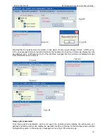
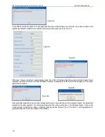
Page 138: ...heckout the available serial ports in the computer automatically and will list them at the Optional Table 4 When login on you must insert the Softdog provided by manufacturer to the computer otherwise cannot be login the system and the window as Fig 4 1 and the Softdog Error would show as follows 5 Be sure the softdog has been inserted to USB port all the time while the software is running otherwi...

Page 139: ...s i e the 7th times password error the window show as Fig 4 5 and then click OK it will exit the program 8 In case the selected serial port is unavailable the window as Fig 4 6 will be display b Detail application manual Main interface of this software as Fig 4 7 detail as follows Fig 4 3 Fig 4 4 Fig 4 5 Fig 4 6 Fig 4 7 ...

Page 140: ...system diagram in Software Application 3 Lock KJR The in Fig 4 7 To lock or unlock the current selected wired controller to limit the wired controller setting the refrigeration system 4 System operate set The in Fig 4 7 To set the operation of the selected refrigeration system 5 Query system parameter The in Fig 4 7 Press this key to query the selected refrigeration system the current operating pa...

Page 141: ...ord error window as Fig 4 14 will show if the new passwords be input do not match the message box as Fig 4 15 will display Click Re login window as Fig 4 16 will display that interface ask user whether re login the system if yes please click OK Click Re login system will close the main interface and enter to the login interface again Click Exit the program to quit the program while click Cancel sy...

Page 142: ... controller modification see Fig 4 21 KJR Name could not empty or pure blank character string pure blank charter string is composed by space and tab c Delete wired controller Select an existing wired controller as above method and click Delete if there is no outdoor module controlled by any wired controller see Fig 4 22 the one could be deleted if there are outdoor modules controlled by wired cont...

Page 143: ...d controller the message box as Fig 4 27 will pop up b Delete sub module Select the sub module which wanted to delete select the wanted delete sub module at the drop down box of Sub module address and click Delete to finish this operation 3 Schedule management includes Weekly timing setting and Error record See Fig 4 28 Click Weekly timing set a window as Fig 4 29 would pop up finish the weekly sc...

Page 144: ...rameter Week Period Time On Time Off Timing Status Control Mode Turn on quantity Mode set and Setting temp d Timing ON OFF key for controlling the weekly timing wired controller See the key in the figure when Weekly Timing Function is ON the key shows OFF see Fig 4 30 once click the key all weekly timing function would be turned off and then the Weekly Timing Function displays OFF while the key sh...

Page 145: ...eleted Click the key window as Fig 4 35 shows click OK to delete Period Successful delete the Period message box as Fig 4 36 will show 1 Detail procedures of add a new Weekly Timing Schedule a Select a wired controller By clicking the System diagram for weekly timing AC wired controller icon at the left side in the wired controller or by selecting the wired controller at the drop down box of KJR A...

Page 146: ...t be at the same time point the following will be not allowed for example if the ON time was 8 00 of Period1 and the OFF time was 8 00 and the OFF time of Period1 was 10 00 and the ON time of Period2 was 10 00 If there is error and then will pops up prompt dialog box display as Fig 4 39 If no Timing Status has been set a message box as Fig 4 40 would pop up If no Control Mode has been set a messag...

Page 147: ...Off selecting then means do not turn off the unit display as Fig 4 45 Timing Status Drive up the weekly timing function in the current period or not Control Mode Automatically drive up mode Mode set Heating Cooling Water Pump Setting temp Setting temp If other parameters have been set click Save key a message box as the same as above 1 Detail procedures of add a new Weekly Timing Schedule will pop...

Page 148: ...the serial port in computer The available serial port source is captured by software and saved at the optional list for user to select Provided that the selected serial port has been occupied once click Apply or Enter a message box as Fig 4 52 will pop up if the serial port as is the current applying port once click Apply or Enter a message box as Fig 4 53 will pop up Fig 4 47 Fig 4 48 Fig 4 49 Fi...

Page 149: ...relevant software information Wired controller lock unlock Provided that the selected wired controller in unlock status the key would display Lock KJR see Fig 4 56 once successful lock the wired controller the message box see Fig 4 57 would display tells user that the setting is successful then the key displays Unlock KJR see Fig 4 58 If the set failed message box Fig 4 59 would display If without...

Page 150: ...s Lock KJR see Fig 4 63 If the set failed message box Fig 4 64 would display tells user that set failed because of timeout Query system parameter Click Query system parameter system will query the operating status display the sub module of 0 address s operation status and display the operative interface according to the selected wired controller refrigeration system In the querying a message box s...

Page 151: ...asn t been selected namely the wired controller address is empty a message box as Fig 4 69 would pop up The query performance failed Provided that malfunction occur the corresponding error code will show in the System Query Provided that protection function perform the corresponding protection code will show in the System Query if move the mouse arrow to the these codes a floating window as the fo...

Page 152: ...le In the querying a message box see Fig 4 72 would pop up Query success see Fig 4 73 to note you the query is successful and update the parameter interface see Fig 4 74 base on the query result whereas Query overtime see Fig 4 75 would display Provided that sub module hasn t been selected namely the sub module address and the corresponding name are empty a message box see Fig 4 76 would pop up Th...

Page 153: ...oating window as the follows Fig 4 77 and 4 78 will appearance to giving the specific error or protection information More parameters Click More Parameters you could query more data See Fig 4 79 If the sub module hasn t been selected a message box as Fig 4 80 would show You must click a certain sub module firstly and then to click the More parameters key more parameter could be queried a message b...

Page 154: ...e System operate set in the conditioner of without wired controller has been selected a message box as Fig 4 82 would show Click the System operate set in the conditioner of although the wired controller has been set all options in the System Set are empty See Fig 4 83 a message box as Fig 4 84 would show Fig 4 79 Fig 4 80 Fig 4 81 Fig 4 82 Fig 4 83 Fig 4 84 ...

Page 155: ...roller separately Do not tick the Uniformly Set Select the wanted set wired controller refrigeration system from the wired controller address column and select the corresponding set parameters which include control Mode Auto Mode set cooling heating Water pump turn off Setting temp Cooling 5 17 Heating 45 50 After set up all above parameters See Fig 4 88 please click the System operate set system ...

Page 156: ...Fig 4 93 will display during the setting Once successful setting a message box as Fig 4 94 will display to inform you Successful System Set whereas Failed System set as Fig 4 95 will display After all setting done a message box see Fig 4 96 will display informing Setting Finish Remark The computer can use the names of serial ports for querying 1 Right click the My Computer and select the Propertie...

Page 157: ...n the Hardware as Fig 4 98 3 The window Device Manager will be showed up after clicking the Device Manager as Fig 4 99 4 Click the icon in front of the Ports COM LPT then can view the port names by the format as COM number these names are the usable serial port names for the computer Note the computer may has more serial ports or no ports as Fig 4 100 Fig 4 97 Fig 4 98 Fig 4 99 Fig 4 100 ...

Page 158: ...S by network variables complying with LonMark standard LonWorks interoperability Guidelines Version 3 4 Compliance LonWorks gateway between LonMark LonTalk protocol andMDPP Private protocol The gateway can convert the LonTalk protocol to the MDPP protocol Connection to 16 MAX Air cooled scroll units Valid address for each unit 0x00 0x0F 15 5 3 Specifications NO FUNCTION DESCRIPTION 1 Processor mem...

Page 159: ...Communication port Communication port 8 Size 31 9cm X 25 1cm X 6 1cm 15 5 4 External dimension There are three installation methods as the following figure Do not install the unit in any other orientation 15 5 5 Connection Method Connection Method 1 291 319 251 268 8 61 15 22 ...

Page 160: ...he one that is intended to access This device consists of one transceivers the following called Main controller for short Main controller is responsible for querying and setting of 16 sets Air cooled Modular units with addresses of 0 15 15 5 6 NetWork variables of setting main controller Air cooled Modular units Max 16 units LONWORKS NET WORK LSQ LONWORKS BMS SYSTEM RS485 P Q E Air cooled Modular ...

Page 161: ...iables which are assigned to the Air cooled Modular system The network variable of Air cooled Modular system 4 input network variables used for setting 8 output network variables used for query As the following figure nciCtrl_Addr 255 0 254 1 253 2 252 3 251 4 250 5 249 6 248 7 247 8 246 9 245 10 244 11 243 12 242 13 241 14 240 15 Corresponding address of wired controller NO Name Name 2 4800bps In...

Page 162: ...ork variable of air cooled modular system Output network variable of air cooled scroll chiller unit system nviSetMode nviSetTemp nviTempDiff nviClrErrorState nvoOutTemp nvoOnNum nvoRunNum nvoSystemMode nvoCool TempHi nvoCoolTempLo nvoHeatTempHi nvoHeatTempLo Air cooled Modular system ...

Page 163: ...eat mode of Air cooled Modular system setting the min value of the total water outlet temperature This network variable only is effective when the nciType being set as 0 otherwise this network variable is invalid value SNVT_hvac_mode SNVT_temp_p HVAC_COOL Cool Mode HVAC_HEAT Heat Mode HVAC_FAN_ONLY Water pump Mode HVAC_OFF Off Mode Setting water outlet temperature Detail data refers to the nviSetT...

Page 164: ...perature paramete rs of unit which address is 1 Water outlet temperature of unit Water inlet temperature of unit This variable is only effective when the nciType being set as 0 Anti Freezing temperature of unit This variable is only effective when the nciType being set as 0 Outdoor temperature T4 This variable is only effective when the nciType being set as 0 Each temperature parameters of unit Th...

Page 165: ...uggested that set the mode the setting temperature to reach the expected effect NO Name Current of Compressor A 5 6 Network variable name nvoCompA Current n SNVT_count 0 250A Current of Compressor B nvoCompB Current n SNVT_count 0 250A Network variable type Date definition Descriptions Compressor A current of unit n means the address of the unit nvoCompACurrent 1 means the Compressor A current of ...

Page 166: ...ies Item Name of accessory Type Qty Shape Usage 1 Installation and operation manual 1 Installation and using instruction 2 The total outlet water temperature test kit LSQWRF65M A C ZL 10 1 Inspection the temperature of total outlet water 3 Wired controller KJRM 120D BMK E 1 Control the system ...

Page 167: ...3482 6 49 3161 34 6 68355 74 1 43498 114 0 42304 5 46 5725 35 6 40021 75 1 38703 115 0 41164 4 44 36 6 13059 76 1 34105 116 0 4006 3 41 5878 37 5 87359 77 1 29078 117 0 38991 2 39 8239 38 5 62961 78 1 25423 118 0 37956 1 37 1988 39 5 39689 79 1 2133 119 0 36954 0 35 2024 40 5 17519 80 1 17393 120 0 35982 1 33 3269 41 4 96392 81 1 13604 121 0 35042 2 31 5635 42 4 76253 82 1 09958 122 0 3413 3 29 90...

Page 168: ...6 82 31060 79 11 15420 132 2 45444 185 0 74820 26 1190 94520 27 78 81040 80 10 79300 133 2 39424 186 0 73358 25 1121 45720 28 75 47360 81 10 44900 134 2 33576 187 0 71982 24 1056 14020 29 72 30020 82 10 12220 135 2 27900 188 0 70606 23 995 10600 30 69 28160 83 9 80400 136 2 22396 189 0 69230 22 938 04500 31 66 39200 84 9 49440 137 2 17150 190 0 67940 21 884 66480 32 63 64860 85 9 20200 138 2 11990...

Page 169: ...720 56 24 75080 109 4 56660 162 1 19368 4 229 49960 57 23 85640 110 4 44620 163 1 16788 5 218 40560 58 23 00500 111 4 32322 164 1 14208 6 207 87060 59 22 17940 112 4 20454 165 1 11800 7 197 91180 60 21 39680 113 4 08930 166 1 09650 8 188 49480 61 20 64000 114 3 97750 167 1 07500 9 179 59380 62 19 90900 115 3 87000 168 1 05436 10 171 16580 63 19 22100 116 3 75992 169 1 03458 11 163 15920 64 18 5502...

Reviews: