background image

MCAC-TSM-2008-02 

Outdoor units   

Outdoor units 

55 

4. Electric 

protection

 Er41

1) Phase 

protection 

of power supply: 

When the chiller is powered on, if there is wrong sequence of power phase, lack of power phase, it will 
show Er41, the chiller can not run. 

2) Compressor 

current 

protection: 

If the operating current of compressor reaches the value below, system stops and shows Er41: 

Capacity ( kW) 

Compressor current value (A) 

Capacity ( kW) 

Compressor current value (A) 

5 18 

10(3N) 

18 

7 18 12 25 

9 32 14 25 

10(1N) 32  16  25 

Values display indication 

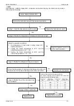
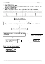
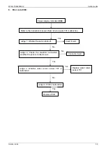
Er41

Judge 1: Whether the phase sequence of the power line is 
wrong connected or one phase of the power line is broken off. 

Connect the power line 
well in sequence. 

Yes 

No 

Judge 2: Compressor current protection 

Check whether the compressor current reaches the value in 
the above table 

Judge 3: PCB is malfunction 

Replace PCB 

No 

Yes 

Check whether the refrigerant 
pipe is air-logged. 

Yes 

Dredge the refrigerant pipe.

Check whether the compressor is locked. 

Replace the compressor. 

Yes 

No 

Summary of Contents for MGC-F05W/N1

Page 1: ...MCAC TSM 2008 02 Contents Contents i Part 1 General Information 2 Part 2 Outdoor units 7 Part 3 Installation 63 Part 4 Controller 79...

Page 2: ......

Page 3: ...tary Chiller is air cooled chiller and heat pump system the chiller itself built in with water pump expansion tank plate heat exchanger it is very simple for installer to install such kind of system P...

Page 4: ...General Information MCAC TSM 2008 02 2 General Information Part 1 General Information 1 Model Names of Outdoor Units 3 2 External Appearance 4 3 Nomenclature 5 4 Features 6...

Page 5: ...Power Supply V ph Hz MGC F05W N1 R410A 5 0kW 220 240 1 50 MGC F07W N1 R410A 7 2kW 220 240 1 50 MGC F09W N1 R410A 9 0kW 220 240 1 50 MGC F10W N1 R410A 10 5kW 220 240 1 50 MGC F10W SN1 R410A 10 5kW 380...

Page 6: ...External Appearance MCAC TSM 2008 02 4 General Information 2 External Appearance MGC F05W N1 MGC F07W N1 MGC F09W N1 MGC F10W S N1 MGC F12W SN1 MGC F14W SN1 MGC F16W SN1...

Page 7: ...02 Nomenclature General Information 5 3 Nomenclature MGC F 14 W S N1 Refrigerant N1 R410A Power Supply S 380 415V 50Hz 3ph 220 240V 50Hz 1ph Outdoor Unit Capacity 14kW F Fixed Speed Type Midea Mini Un...

Page 8: ...r pressure gauge inspect water pressure all the time 5 Flexible control built in with controller inside the chiller and can be controlled in the room by remote control keyboard 6 Built in with voltage...

Page 9: ...utdoor units 1 Specification 8 2 Dimensions unit mm 12 3 Service Space unit mm 15 4 Piping Diagram 16 5 Wiring Diagrams 17 6 Electric Characteristics 20 7 Capacity Tables 21 8 Operation Limits 37 9 So...

Page 10: ...pper tube Inner grooved copper tube Coil length height width mm 893 880 893 880 Outdoor coil Number of circuits 4 7 Type RS15 6 3 WILO RS15 6 3 WILO Input H M L W 93 67 46 93 67 46 Water pump Outdoor...

Page 11: ...height width mm 635 1220 66 635 1220 66 Outdoor coil Number of circuits 6 6 Type RL25 8 5 RL25 8 5 Input H M L W 210 175 120 210 175 120 Water pump Outdoor air flow m 3 h 6450 4250 6500 4300 Throttle...

Page 12: ...ngth height width mm 807 1188 38 1 945 1188 38 1 Outdoor coil Number of circuits 7 7 Type RL25 8 5 RL25 8 5 Input H M L W 210 175 120 210 175 120 Water pump Outdoor air flow m 3 h 6465 4270 6470 4280...

Page 13: ...h height width mm 718 1220 66 937 1188 57 15 Outdoor coil Number of circuits 12 14 Type RL25 8 5 RL25 8 5 Input H M L W 210 175 120 210 175 120 Water pump Outdoor air flow m3 h 6500 4300 6550 4483 Thr...

Page 14: ...Specification MCAC TSM 2008 02 12 Installation 2 Dimensions unit mm 2 1 MGC F05W N1 MGC F07W N1...

Page 15: ...MCAC TSM 2008 02 Outdoor units Outdoor units 13 2 2 MGC F09W N1 MGC F10W N1 MGC F10W SN1...

Page 16: ...Specification MCAC TSM 2008 02 14 Installation 2 3 MGC F12W SN1 MGC F14W SN1 MGC F16W SN1...

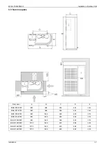
Page 17: ...n A B C D E MGC F05W N1 990 966 354 624 366 MGC F07W N1 990 966 354 624 366 MGC F09W N1 940 1245 360 600 376 MGC F10W N1 940 1245 360 600 376 MGC F10W SN1 940 1245 360 600 376 MGC F12W SN1 1070 1249 4...

Page 18: ...o Name No Name 1 Compressor 6 Capillary 11 Water differential pressure switch 2 High pressure switch 7 Liquid receiver 12 Accumulator 3 4 way valve 8 Plate heat exchanger 13 Low pressure switch 4 Cond...

Page 19: ...MCAC TSM 2008 02 Outdoor units Outdoor units 17 5 Wiring Diagrams 5 1 MGC F05W N1 MGC F07W N1...

Page 20: ...Specification MCAC TSM 2008 02 18 Installation 5 2 MGC F09W N1 MGC F10W N1...

Page 21: ...MCAC TSM 2008 02 Outdoor units Outdoor units 19 5 3 MGC F10W SN1 MGC F12W SN1 MGC F14W SN1 MGC F16W SN1...

Page 22: ...1 2 0 8 2 MGC F10W N1 50Hz 220 240V 1ph 198V 254V 24 5 32 35 123 19 5 0 1 2 0 8 2 MGC F10W SN1 50Hz 380 415V 3ph 342V 440V 9 2 10 5 20 64 7 3 0 1 2 0 8 2 MGC F12W SN1 50Hz 380 415V 3ph 342V 440V 12 1...

Page 23: ...Pa 1 8 1 8 1 8 1 9 1 9 1 9 Pat 2 1 2 1 2 1 2 2 2 2 2 2 Qev 0 83 0 84 0 86 0 88 0 89 0 91 35 0 Pev 18 5 19 8 21 0 22 5 24 0 25 5 Pf 4 6 4 7 4 9 5 0 5 1 5 2 Pa 1 9 1 9 1 9 2 0 2 0 2 0 Pat 2 2 2 2 2 2 2...

Page 24: ...2 7 2 7 2 7 Pat 2 9 2 9 2 9 3 0 3 0 3 0 Qev 1 20 1 22 1 24 1 26 1 27 1 29 35 0 Pev 32 5 33 8 35 0 36 5 38 0 39 5 Pf 6 8 6 9 7 1 7 2 7 3 7 4 Pa 2 7 2 7 2 7 2 8 2 8 2 8 Pat 3 0 3 0 3 0 3 1 3 1 3 1 Qev...

Page 25: ...3 3 3 Pat 3 4 3 4 3 5 3 6 3 6 3 6 Qev 1 3 1 3 1 4 1 4 1 5 1 5 35 Pev 28 0 30 4 33 9 35 0 38 0 420 Pf 7 0 7 3 7 5 7 7 8 0 8 3 Pa 3 4 3 4 3 5 3 6 3 6 3 6 Pat 3 7 3 7 3 8 3 9 3 9 3 9 Qev 1 2 1 3 1 3 1 4...

Page 26: ...3 4 3 4 3 5 3 5 Pat 3 8 3 8 3 9 3 9 4 0 4 0 Qev 1 7 1 7 1 8 1 9 1 9 2 0 35 Pev 27 0 27 5 30 0 32 0 32 4 34 0 Pf 9 4 9 7 10 0 10 3 10 6 11 0 Pa 3 6 3 6 3 7 3 7 3 8 3 8 Pat 4 1 4 1 4 2 4 2 4 3 4 3 Qev...

Page 27: ...3 3 4 3 4 3 5 3 5 Pat 3 8 3 8 3 9 3 9 4 0 4 0 Qev 1 7 1 7 1 8 1 9 1 9 2 0 35 Pev 27 0 27 5 30 0 32 0 32 4 34 0 Pf 9 4 9 7 10 0 10 3 10 6 11 0 Pa 3 6 3 6 3 7 3 7 3 8 3 8 Pat 4 1 4 1 4 2 4 2 4 3 4 3 Qev...

Page 28: ...4 3 4 3 4 3 Pat 4 8 4 8 4 8 4 9 4 9 4 9 Qev 2 0 2 0 2 1 2 1 2 2 2 2 35 Pev 21 1 23 2 25 4 27 0 28 8 30 0 Pf 10 9 11 2 11 5 11 8 12 1 12 4 Pa 4 5 4 5 4 5 4 6 4 6 4 6 Pat 5 1 5 1 5 1 5 2 5 2 5 2 Qev 1 9...

Page 29: ...6 4 7 4 7 4 7 Pat 5 1 5 1 5 1 5 2 5 2 5 2 Qev 2 3 2 4 2 4 2 5 2 5 2 5 35 Pev 24 0 25 6 26 0 27 6 28 1 28 4 Pf 12 5 12 8 13 1 13 4 13 7 14 0 Pa 5 1 5 1 5 1 5 2 5 2 5 2 Pat 5 6 5 6 5 6 5 7 5 7 5 7 Qev...

Page 30: ...0 6 1 6 1 6 1 Pat 6 5 6 5 6 5 6 6 6 6 6 6 Qev 2 6 2 6 2 7 2 7 2 8 2 8 35 Pev 28 2 29 5 31 0 32 3 34 0 35 1 Pf 14 2 14 5 14 8 15 1 15 4 15 7 Pa 5 5 5 5 5 5 5 6 5 6 5 6 Pat 6 0 6 0 6 0 6 1 6 1 6 1 Qev...

Page 31: ...1 7 1 9 Pat 1 7 1 8 2 2 2 Qc 0 96 0 95 0 95 0 93 7 Pc 23 9 23 4 23 22 9 Pt 6 1 6 1 6 6 Pa 1 4 1 5 1 7 1 9 Pat 1 7 1 8 2 2 2 Qc 1 05 1 05 1 03 1 03 10 Pc 27 8 27 5 27 1 27 Pt 6 5 6 5 6 5 6 4 Pa 1 4 1 6...

Page 32: ...t 2 6 2 7 2 9 3 1 Qc 1 34 1 32 1 32 1 31 7 Pc 36 9 36 4 36 35 9 Pt 8 3 8 3 8 2 8 2 Pa 2 3 2 4 2 6 2 8 Pat 2 6 2 7 2 9 3 1 Qc 1 43 1 43 1 41 1 41 10 Pc 40 8 40 5 40 1 40 Pt 8 7 8 7 8 7 8 6 Pa 2 3 2 5 2...

Page 33: ...t 3 3 3 5 3 8 4 1 Qc 1 6 1 6 1 6 1 6 7 Pc 48 5 48 2 47 8 47 4 Pt 9 5 9 5 9 5 9 4 Pa 3 1 3 3 3 6 3 9 Pat 3 4 3 6 3 9 4 2 Qc 1 7 1 7 1 7 1 7 10 Pc 56 8 56 2 55 7 55 3 Pt 10 2 10 2 10 2 10 1 Pa 3 2 3 4 3...

Page 34: ...3 8 4 1 4 3 4 6 Qc 2 0 2 0 2 0 1 9 7 Pc 37 2 35 8 34 5 33 1 Pt 12 3 12 2 12 1 12 0 Pa 3 4 3 7 3 9 4 2 Pat 3 9 4 2 4 4 4 7 Qc 2 1 2 1 2 1 2 1 10 Pc 40 5 40 0 39 2 38 8 Pt 13 8 13 7 13 6 13 5 Pa 3 5 3...

Page 35: ...t 3 8 4 1 4 3 4 6 Qc 2 0 2 0 2 0 1 9 7 Pc 37 2 35 8 34 5 33 1 Pt 12 3 12 2 12 1 12 0 Pa 3 4 3 7 3 9 4 2 Pat 3 9 4 2 4 4 4 7 Qc 2 1 2 1 2 1 2 1 10 Pc 40 5 40 0 39 2 38 8 Pt 13 8 13 7 13 6 13 5 Pa 3 5 3...

Page 36: ...Pat 4 5 4 8 5 1 5 4 Qc 2 3 2 3 2 3 2 3 7 Pc 44 0 43 6 43 1 42 8 Pt 14 4 14 3 14 2 14 1 Pa 4 0 4 3 4 6 4 9 Pat 4 6 4 9 5 2 5 5 Qc 2 5 2 5 2 5 2 5 10 Pc 38 0 37 6 37 2 37 0 Pt 15 9 15 8 15 7 15 6 Pa 4 1...

Page 37: ...t 4 6 5 0 5 5 6 0 Qc 2 8 2 8 2 8 2 8 7 Pc 31 2 31 1 31 0 31 0 Pt 17 6 17 5 17 4 17 4 Pa 17 6 17 5 17 4 17 4 Pat 17 6 17 5 17 4 17 4 Qc 3 1 3 1 3 1 3 1 10 Pc 36 4 36 2 36 0 35 9 Pt 19 8 19 7 19 6 19 4...

Page 38: ...5 3 Pat 4 1 4 5 5 0 5 6 Qc 2 7 2 7 2 7 2 7 7 Pc 30 2 30 1 30 30 Pt 16 9 16 8 16 7 16 6 Pa 3 9 4 3 4 8 5 3 Pat 4 2 4 6 5 1 5 6 Qc 3 0 3 0 3 0 3 0 10 Pc 35 4 35 2 35 34 8 Pt 19 18 9 18 8 18 7 Pa 4 0 4...

Page 39: ...MCAC TSM 2008 02 Outdoor units Outdoor units 37 8 Operation Limits...

Page 40: ...to pipeline or keep power on at standby or off status and ensure that water is contained inside of unit 2 When ambient temperature lower 5 running cooling mode must be charged antifreeze Refer to uppe...

Page 41: ...ts 39 9 Sound Level 1 0m Microphone Outdoor Unit Unit Number Model Noise level dB A 1 MGC F05W N1 55 2 MGC F07W N1 56 3 MGC F09W N1 58 49 4 MGC F10W N1 60 50 5 MGC F10W SN1 58 48 6 MGC F12W SN1 59 49...

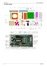
Page 42: ...Specification MCAC TSM 2008 02 40 Installation 10 Exploded View 10 1 MGC F05W N1...

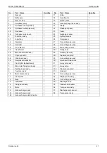
Page 43: ...ormer 1 28 2 Safety valve 1 5 6 Main control board ass y 1 29 Suction pipe ass y 1 5 7 Urgency switch 1 29 1 Pressure controller 1 5 8 Filter board ass y 1 30 Connecting pipe ass y 1 5 9 Compressor ca...

Page 44: ...Specification MCAC TSM 2008 02 42 Installation 10 2 MGC F07W N1...

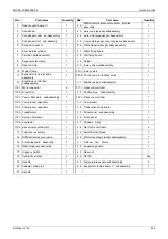
Page 45: ...Main control board ass y 1 28 2 Safety valve 1 5 7 Urgency switch 1 29 Suction pipe ass y 1 5 8 Filter board ass y 1 29 1 Pressure controller 1 5 9 Compressor capacitor 1 30 Connecting pipe ass y 1 6...

Page 46: ...Specification MCAC TSM 2008 02 44 Installation 10 3 MGC F09W N1 MGC F10W N1...

Page 47: ...2 Electronic control box subassembly 1 31 Discharge pipe subassembly 1 12 1 Motor capacitor 2 31 1 Pressure controller 1 12 2 E part box 1 32 Suction pipe subassembly 1 12 3 Power filter plate subasse...

Page 48: ...Specification MCAC TSM 2008 02 46 Installation 10 4 MGC F10W SN1...

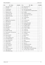
Page 49: ...31 Discharge pipe ass y 1 12 2 E part box 1 31 1 Pressure controller 1 12 3 Filter board ass y 1 32 Suction pipe ass y 1 12 4 Transformer 1 32 1 Pressure controller 1 12 5 AC contactor 1 33 Compresso...

Page 50: ...Specification MCAC TSM 2008 02 48 Installation 10 5 MGC F12W SN1 MGC F16W SN1...

Page 51: ...rd ass y 1 27 6 Pipe joint 3 8 7 AC contactor 1 27 7 Pipe joint 2 9 Connecting pipe ass y 1 27 7 Rubber gasket 2 9 1 Copper nut 2 28 Suction pipe ass y 1 10 Top cover ass y 1 28 1 Pressure controller...

Page 52: ...Specification MCAC TSM 2008 02 50 Installation 10 6 MGC F14W SN1...

Page 53: ...1 27 1 Make up water valve 1 8 9 Power supply blue wire 1 27 2 Check valve tie in 1 8 10 Gas protection signal wire 1 27 3 Safety valve 1 8 11 Liquid protection signal wire 1 27 4 Water inlet pipe tie...

Page 54: ...prevention alarm manual reset Er61 Water outlet sensor T02 malfunction automatic reset Er62 Coil sensor T03 malfunction automatic reset Er60 Water return sensor T01 malfunction automatic reset Er20 W...

Page 55: ...ient temperature is 10 43 3 heating the indoor temperature is 30 and the outdoor temperature is 15 24 Stop the operation and run it at the normal condition No Yes Judge 3 Whether the refrigerant charg...

Page 56: ...hether the temperature of external and inlet water is low Yes Check the operation conditions 1 the temperature of inlet water cooling below 20 heating below 45 2 cooling the indoor temperature is 17 a...

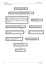
Page 57: ...alue A Capacity kW Compressor current value A 5 18 10 3N 18 7 18 12 25 9 32 14 25 10 1N 32 16 25 Values display indication Er41 Judge 1 Whether the phase sequence of the power line is wrong connected...

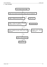
Page 58: ...c heater start working when water outlet temperature T02 6 water pump and electric heater stop working Judge 2 Check whether the electric heater is well Supply the power No Yes Replace the electric he...

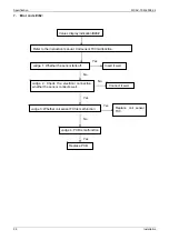
Page 59: ...er delivery sensor T02 malfunction Judge 1 Whether the sensor falls off Insert it well Yes No Judge 2 Check the electrical connection whether the sensor connects well No Connects it well Yes Judge 3 W...

Page 60: ...tion manual Coil sensor T03 malfunction Judge 1 Whether the sensor falls off Insert it well Yes No Judge 2 Check the electrical connection whether the sensor connects well No Connect it well Yes Judge...

Page 61: ...Water return sensor T01 malfunction Judge 1 Whether the sensor falls off Insert it well Yes No Judge 2 Check the electrical connection whether the sensor connects well No Connects it well Yes Judge 3...

Page 62: ...is close Close the differential pressure switch No Yes Judge 2 Check whether the pump is setting high No Setting the pump in high Yes Judge 3 Check whether the air is in water circuit Vent the air Ju...

Page 63: ...Judge Whether the three connecting lines red blue and black are wrong connected Connect them well in right sequence Yes Refer to the instruction manual Remote keyboard communication error Values displ...

Page 64: ...red by manual reset please do as follow on the control interface Press esc set in the main screen The label PAr will appear Scroll with UP and DOWN to find the FnC label Press set The label dEF will a...

Page 65: ...its 63 Part 3 Installation 1 General Information 64 2 Description of Standard Unit 65 3 Installation of Outdoor Unit 66 4 Hydraulic Connection 68 5 Electrical Connection 71 6 Checking and Starting Up...

Page 66: ...hildren with reduced physical sensory or mental capabilities or lack of experience and knowledge unless they have been given supervision or instruction concerning use of the appliance by a person resp...

Page 67: ...starting torque and automatic venting of impeller chamber Pump assembly Pump assembly with expansion tank safety valve auto water replenishing assembly pressure gauge and pump Condensing coil Made fr...

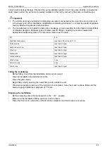
Page 68: ...k or similar bearing in mind the weight distribution of the unit To lift the unit insert tubes long enough to allow positioning of the lifting slings and safety pins in the feet on the unit To avoid t...

Page 69: ...nsion A B C D E MGC F05W N1 990 966 354 624 366 MGC F07W N1 990 966 354 624 366 MGC F09W N1 940 1245 360 600 376 MGC F10W N1 940 1245 360 600 376 MGC F10W SN1 940 1245 360 600 376 MGC F12W SN1 1070 12...

Page 70: ...t or a differential pressure switch inlet outlet 5 Two thermometers inlet and outlet 6 An inlet filter as close as possible to the evaporator and positioned to allow easy access for routine maintenanc...

Page 71: ...priate treatment systems For reference values see the table PH 6 8 Electrical conductivity less than 200 mV cm 25 C Chlorine ions less than 50 ppm Sulphuric acid ions less than 50 ppm Total iron less...

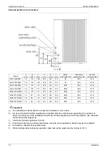
Page 72: ...SN1 78 84 174 297 148 148 R5 4 G1 2 G1 2 MGC F16W SN1 78 84 174 297 148 148 R5 4 G1 2 G1 2 Important a The installation must be filled to a pressure of between 1 and 2 bars b It is recommended that t...

Page 73: ...m with a suitable device to protect against short circuits and leakage to earth isolating the installation from other equipment Voltage must be within a tolerance of 10 of the rated power supply volta...

Page 74: ...50Hz Auxiliary Connection All terminals referred to in the explanations below are to be found on the terminal board inside the electrical panel and described as installer terminals Remote start up an...

Page 75: ...r 220 240 1 50 220 240 1 50 220 240 1 50 220 240 1 50 Circuit breaker fuse A 25 20 30 25 40 25 40 35 Power wiring mm 2 3 2 5 3 2 5 3 4 0 3 4 0 Ground wiring mm 2 2 5 2 5 4 0 4 0 Outdoor Indoor connect...

Page 76: ...carried out correctly Voltage is within a tolerance of 10 of the rated voltage for the unit The unit is correctly earthed All electrical and hydraulic connections are tight and have been completed cor...

Page 77: ...to signal that voltage is present 6 3 Activating and deactivating the unit Set the remote keyboard A6 if present to ON To ACTIVATE and DEACTIVATE the COOLING and HEATING functions use the ST542 contr...

Page 78: ...g from the pressure probe thus enabling heat exchange to be increased and or decreased maintaining the condensing or evaporation temperature practically constant The fan functions independently of the...

Page 79: ...itions there should be no need for the Technical Assistance Service to intervene to check the refrigerant gas However over time small leaks may develop at the joints leading to loss of refrigerant and...

Page 80: ...periods After deactivating the chiller Make sure the remote switch SA 2 is in the Standby position or alternatively disconnect the unit from the power supply Make sure the remote keyboard if present...

Page 81: ...MCAC TSM 2008 02 Running and Maintenance Installation 79 Part 4 Controller 1 Standard Controller 80...

Page 82: ...ncreases a value Goes to the next label Manual defrost activation DOWN DOWN Decreases a value Goes to the previous label Local ON OFF Esc ape Output Without saving new settings Exit without saving new...

Page 83: ...uts dO dO1 dO2 dO3 dO4 dO5 dO6 Dynamic Digital outputs CL HOUr dAtE yeaR Clock Yes AL Er00 Er99 Dynamic Alarms SP Value Set points set Yes Sr Value Real set point Hr CP01 CP02 PU01 PU02 Dynamic Runnin...

Page 84: ...pending on the setting on the digital controller the unit will operate in cooling or in heating mode Procedure a Connect the cable to the appropriate terminals as shown or the wiring diagram b Fix the...

Page 85: ...02 Standard Controller Controller 83 2 Select Operating Mode There are three different operating modes Standby mode StbY Heat mode Cooling mode Instructions are provided below on how to change the op...

Page 86: ...Standard Controller MCAC TSM 2008 02 84 Controller 3 Select the Clock CL...

Page 87: ...d Controller Controller 85 4 Modifying a parameter Instructions are provided below on how to change a machine parameter By way of example let s look at the CF configuration parameters folder parameter...

Page 88: ...Standard Controller MCAC TSM 2008 02 86 Controller 5 Set the set point SP By way of example we will change the set point value in COOL mode by 12 0 degrees centigrade to12 5 degrees centigrade...

Page 89: ...MCAC TSM 2008 02 Standard Controller Controller 87...

Page 90: ...ar on the display Use the UP and DOWN keys to scroll the other labels until you find the Hr label Press the set key to view the first label which in this case is the running time for compressor 1 CP01...

Page 91: ...g folder EUr Press esc set in the main screen The label PAr will appear Scroll with UP and DOWN to find the FnC label Press set The label dEF will appear Scroll with UP and DOWN to find the EUr label...

Page 92: ...n error message will be shown alternating with the error alert and the main display The ALARM LED will be permanently on An error can be acknowledged by pressing any key once After pressing any key th...

Page 93: ...conditions fall within the limits specified in the table of technical data Check that the compressor current input is less than the maximum indicated in the table of technical data In three phase mod...

Page 94: ...Standard Controller MCAC TSM 2008 02 92 Controller...

Reviews: