background image

Midea R410A Full DC Inverter Split Type Series Technical Manual                            MCAC-UTSM-201406 

61 

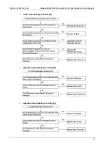
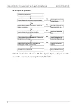
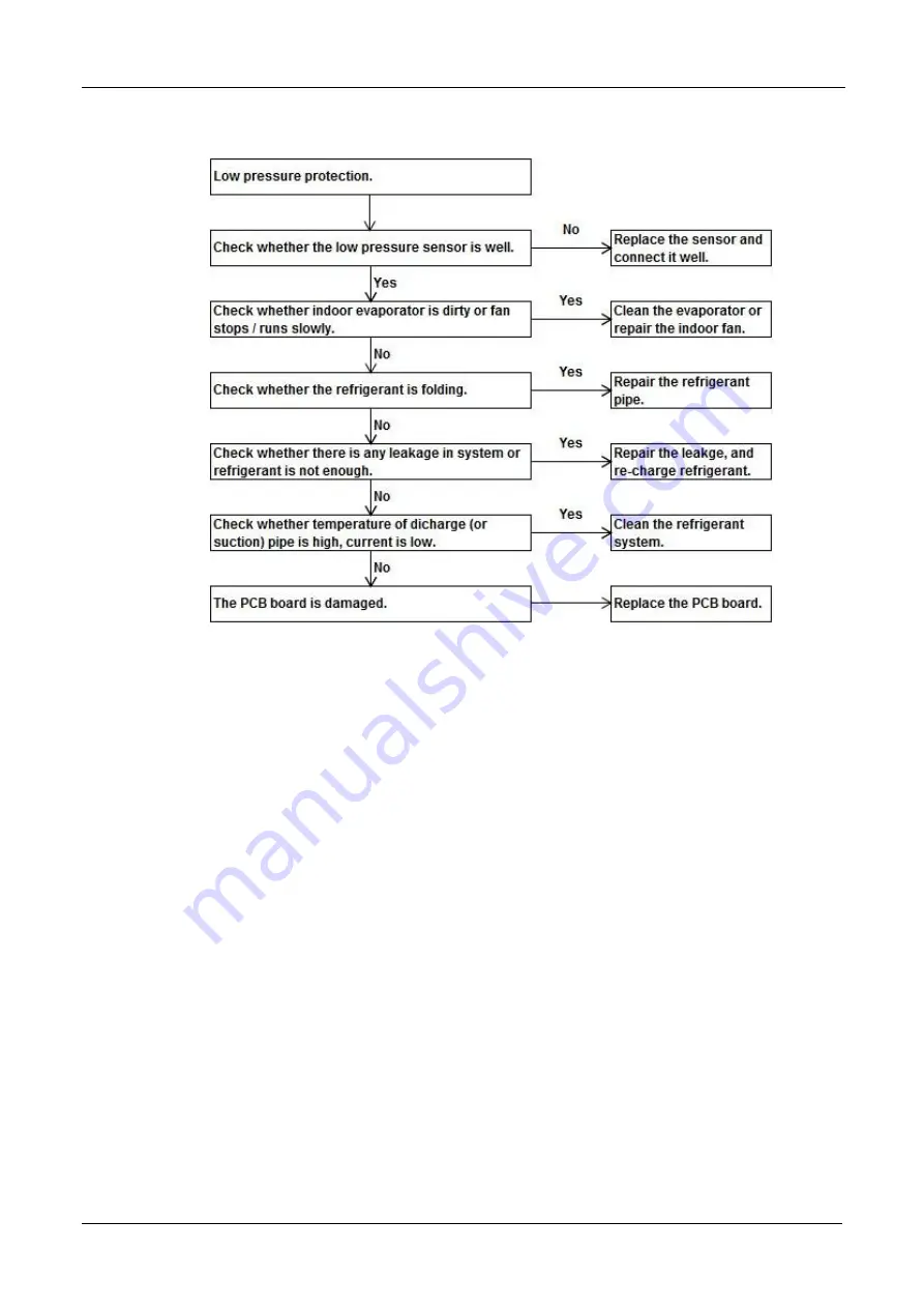
P2: Low pressure protection 


Notes: There are three times in  60 minutes, 

‘H5’ will be displayed. Repower-on, the protection will be 

canceled. At the same time, the reason of protection should be settled. 


Summary of Contents for MHC-96HWD1N1

Page 1: ...e Series 50Hz Technical Manual Applicable Model Indoor unit Outdoor unit Midea reserves the right to discontinue or change specification or designs at any time without notices and without incurring ob...

Page 2: ...a R410A Full DC Inverter Split Type Series Technical Manual MCAC UTSM 201406 1 Content Part 1 General information 2 Part 2 Indoor Unit 5 Part 3 Outdoor Unit 17 Part 4 Installation 22 Part 5 Controller...

Page 3: ...MCAC UTSM 201406 Midea R410A Full DC Inverter Split Type Series Technical Manual 2 Part 1 General information 1 Model Names of Indoor Outdoor Units 3 2 External Appearance 3 3 Nomenclature 4...

Page 4: ...1 Model Names of Indoor Outdoor Units Type Indoor unit Outdoor unit Model Power supply Model Power supply Hi static pressure duct type MHC 96HWD1N1 220 240V 1Ph 50Hz MOVG 96HD1N1 R 380 415V 3Ph 50Hz 2...

Page 5: ...nverter Control type Wired controller H Heat pump Nominal cooling capacity 96 1 000Btu h Series number C type High static pressure duct type Midea 3 2 Outdoor unit M O V G 96 H D1 N1 R Power supply 38...

Page 6: ...C UTSM 201406 5 Part 2 Indoor Unit 1 Features 6 2 Specifications 7 3 Dimensions Unit mm 8 4 Service Space 8 5 Refrigerant circuit 9 6 Wiring Diagrams 10 7 Capacity Table 13 8 Static Pressure Curve 15...

Page 7: ...by the location of lighting fixtures or room structure Air inlet and outlet flanges are standard and easy for duct connection Multi diffusers from one indoor unit supply airflow to multi rooms at the...

Page 8: ...Motor model Quantity WZDK750 38GS W 1 Speed Hi med lo r min 1 250 1 160 1 090 Coil Type Copper tube and aluminum fin Tube size mm 9 52 No of rows 4 Fin spacing mm 1 5 Tube pitch a row pitch b mm 25 4...

Page 9: ...MCAC UTSM 201406 Midea R410A Full DC Inverter Split Type Series Technical Manual 8 3 Dimensions Unit mm Pipe side view 4 Service Space Top view...

Page 10: ...Midea R410A Full DC Inverter Split Type Series Technical Manual MCAC UTSM 201406 9 5 Refrigerant circuit...

Page 11: ...MCAC UTSM 201406 Midea R410A Full DC Inverter Split Type Series Technical Manual 10 6 Wiring Diagrams...

Page 12: ...Midea R410A Full DC Inverter Split Type Series Technical Manual MCAC UTSM 201406 11...

Page 13: ...MCAC UTSM 201406 Midea R410A Full DC Inverter Split Type Series Technical Manual 12...

Page 14: ...23 01 26 09 22 38 24 99 21 75 23 9 21 12 22 59 20 36 19 0 29 58 22 78 28 55 22 08 27 53 21 37 26 51 20 68 25 14 20 33 23 51 19 92 20 0 30 81 21 90 29 5 21 09 28 2 20 28 26 89 19 48 25 59 18 67 24 02 1...

Page 15: ...2 20 32 20 34 27 34 27 19 0 20 93 20 93 22 34 22 34 23 73 23 73 25 13 25 13 26 54 26 54 29 41 29 41 31 44 31 44 33 47 33 47 21 0 20 51 20 51 21 89 21 89 23 24 23 24 24 62 24 62 26 00 26 00 28 70 28 70...

Page 16: ...atic Pressure Curve 9 Electric Characteristics Model Indoor Unit Power Supply IFM Hz Voltage Min Max MCA MFA kW FLA MHC 96HWD1N1 50 220 240V 198V 254V 6 375 16 0 75 5 1 Note MCA Min Current Amps A MFA...

Page 17: ...uction Discharge Microphone 1 4m Duct 11 Accessories Name Qty Purpose Owner manual 1 Installation manual 1 Restriction assembly 1 Connect to system Water connective pipe 1 Connect to water drainage pi...

Page 18: ...ull DC Inverter Split Type Series Technical Manual MCAC UTSM 201406 17 Part 3 Outdoor Unit 1 Specifications 18 2 Dimension 19 3 Service Space 19 4 Wiring Diagrams 20 5 Electric Characteristics 21 6 So...

Page 19: ...tor speed rpm 730 Coil Type Copper tube and aluminum fin Tube size mm 7 No of rows 3 Fin space mm 1 5 Tube pitch a row pitch b mm 21 13 37 Coil W H mm 2 800 798 Number of circuits 18 Refrigerant pipe...

Page 20: ...0A Full DC Inverter Split Type Series Technical Manual MCAC UTSM 201406 19 2 Dimension Front view Left view Unit mm Top view 3 Service Space A B C D E Installation space 1 500mm 2 000mm 2 000mm 1 500m...

Page 21: ...MCAC UTSM 201406 Midea R410A Full DC Inverter Split Type Series Technical Manual 20 4 Wiring Diagrams...

Page 22: ...Hz Voltage Min Max MCA TOCA MFA MSC RLA KW FLA MOVG 96HD1N1 R 50 380 415V 342V 440V 60 50 70 110 17 0 75 5 5 Remark MCA Min Current Amps A TOCA Total Over current Amps A MFA Max Fuse Amps A MSC Max St...

Page 23: ...t 4 Installation 1 Notes 23 2 Installation of Duct Type Indoor Units 24 3 Installation of Outdoor Units 28 4 Connection of Refrigerant Pipe 32 5 Heat Insulation of Refrigerant Pipe 40 6 Electric Conne...

Page 24: ...e the air contains much salt Hot ring area where corrosive gases exist e g sulfide gas Factories where the supply voltage fluctuates seriously Inside a car or cabin Place like kitchen where oil permea...

Page 25: ...pe Indoor Units 2 1 Installating indoor units As the following picture when install the indoor unit select the enough solid and level site with enough space for installation and maintance The inspecti...

Page 26: ...new concrete roughcast environment please use embedded bolts embedded pulling plugs and stick harness On steel bar have some holes to hang pipe and embed screw bolts When in steel beam and girder stru...

Page 27: ...at an easy to maintain place such as intake pipe If without the filter the duct will gether on the air heat exchanger and lead to fault and water leak of the air conditioner In order to suppress nois...

Page 28: ...ical Manual MCAC UTSM 201406 27 View of air inlet side Unit mm All pipelines must be connected closely and soundly without leak of air The pipelines must be adiabatic and free from condensation The ke...

Page 29: ...joint The drain of water is natural In the construction the external pipe slants downward at a gradient of 1 50 1 100 The number of bends and folds of the drain pipe should not exceed 2 Try to avoid b...

Page 30: ...also meet the requirement of the minimum installation space of the unit When carring the unit the angle of inclination should not be more than 15 to avoid overturn of the unit Rolling handling severa...

Page 31: ...he foundation bolt is shown in following picture To avoid back flow of the air in the condenser and operational faults of the unit the spaces between the unit and the obstacle are also given in the fo...

Page 32: ...of installation foundation Damping devices must be provided between the unit and its foundation By means of the 15mm diameter installation holes on the steel frame of the unit base the unit can be fas...

Page 33: ...on the foundation with the provided holes After the unit is placed on the foundation the damper connected with the unit should not be moved and the central clamp nut is not allowed to be tightened be...

Page 34: ...wise the oxidized chips may block refrigerating circulatory system As following picture when brazing the indoor and outdoor connective pipes pad a sheet metal under the valve avoids the flame burning...

Page 35: ...supplied through the tubing while it is being brazed because the temperature required is high enough to cause oxidation of the copper unless an inert atmosphere is provided The flow of dry nitrogen s...

Page 36: ...the liquid line service port Braze the liquid line to the high pressure valve liquid valve at the outdoor unit Be sure to wrap the valve body with a wet rag Allow the nitrogen to continue flowing Care...

Page 37: ...Never attempt to repair any brazed connections while the system is under pressure Personal injury could result After the pipes between the indoor unit and the outdoor unit are connected replenish comp...

Page 38: ...the square head cover of valves A and B completely Use refrigerant tank to expel air Screw up the pipe nuts at A B C and D completely Loosen and remove the square head cover and maintenance orifice nu...

Page 39: ...on completion of vacuuming tighten the low pressure handle of the manifold valve completely and stop the vacuum pump Keep extracting air for over 15 minutes Check whether the multi meter points at 1 0...

Page 40: ...1m pipe length 12 7mm 0 12kg Note Please check and record the replenished quantity of the air conditioner Refrigerant leak precautions This air conditioner uses refrigerant R410A R410A is safe refrige...

Page 41: ...ntilation is impossible please install the leakage detection alarm device linked with the mechanical ventilation device 5 Heat Insulation of Refrigerant Pipe In order to prevent faults caused by conde...

Page 42: ...r leak 6 Electric Connection 6 1 Caution Use special power supply for the air conditioner Design power supplies specific to the indoor unit and outdoor unit The supply voltage must comply with the nom...

Page 43: ...rding to the national rule The appliance shall be installed in accordance with national wiring regulations 6 2 Specifications of power supply Model MHC 96HWD1N1 MOVG 96HD1N1 R Power 220 240V 1Ph 50Hz...

Page 44: ...re pay attention to the phase sequence of the power supply If the phase sequence is reversed the compressor will not start Meanwhile the fault indicator of the outdoor electric control board will ligh...

Page 45: ...R410A Full DC Inverter Split Type Series Technical Manual 44 7 Duct Design Scheme Examples of construction and ventilation pipeline design scheme Flowering hidden series Construction and ventilation...

Page 46: ...adopt fire resistant materials Those materials other materials Those materials other shall not be applied 3 The heat insulation material must be glass wool 4 1 Install the unit at the air inlet so tha...

Page 47: ...cooling only model 9 1 The lengthwise adjustable model which diffuses air at a 360 angle 2 With the change of the cooling heating air flow the horizontal and vertical distance of the fan can be adjus...

Page 48: ...ircles 3 Use ventilation pipe specific tapes instead of ordinary adhesive tapes In order to ensure the installation quality and durability it is necessary to use the auxiliary materials of standard sp...

Page 49: ...nditioner The system does not run After pressing the ON OFF button the system does not run immediately If the Run indicator is on it indicates the air conditioner runs in the normal status It does not...

Page 50: ...k may occur when the air conditioner starts or stops running That is the sound raised because the plastic assemblies inflate or deflate when the temperature changes Dust is blown out of the indoor uni...

Page 51: ...handing The system does not run Power supply fails Operate it after power supply resumes and connect the power supply properly The power switch is not connected The fuse blows out or the circuit break...

Page 52: ...t quantity Symptom Possible causes Way of handing The cooling effect is poor The refrigerant is excessive or deficient Detect leak and fill the refrigerant of a correct quantity Air or non condensable...

Page 53: ...G ON display disappears Check whether the time set on the time has expired When it comes to the set time of starting operation of the air conditioner the air conditioner will start running automatical...

Page 54: ...Communication error between indoor and outdoor unit Operation lamp flashing or show E2 T1 room temperature sensor error Operation lamp flashing or show E3 T2 pipe temperature sensor error Operation la...

Page 55: ...MCAC UTSM 201406 Midea R410A Full DC Inverter Split Type Series Technical Manual 54 Timer lamp flashing or show E1 Operation lamp flashing or show E2 Operation lamp flashing or show E3...

Page 56: ...MCAC UTSM 201406 55 Operation lamp flashing or show E4 Notes T2B temperature sensor is used to detect the refrigerant temperature of evaporator s outlet Timer lamp flashing or show E6 Alarm lamp flas...

Page 57: ...60 minutes P0 Top temperature protection of compressor Display H6 if three times in 100 minutes P1 High pressure protection or high temperature protection of discharge sensor P2 Low pressure protectio...

Page 58: ...R410A Full DC Inverter Split Type Series Technical Manual MCAC UTSM 201406 57 E1 Phase sequence error E2 Indoor outdoor unit communication error E4 Ambient temperature T4 pipe temperature T3 sensor e...

Page 59: ...MCAC UTSM 201406 Midea R410A Full DC Inverter Split Type Series Technical Manual 58 E5 Voltage error E7 Discharge sensor error E9 Eeprom error...

Page 60: ...ar chip IR341 communication error H1 Between main chip and 0537 chip communication error P0 Top temperature protection of compressor P4 Discharge temperature protection Notes There are three times in...

Page 61: ...MCAC UTSM 201406 Midea R410A Full DC Inverter Split Type Series Technical Manual 60 P1 High temperature protection or high temperature protection of discharge sensor...

Page 62: ...e Series Technical Manual MCAC UTSM 201406 61 P2 Low pressure protection Notes There are three times in 60 minutes H5 will be displayed Repower on the protection will be canceled At the same time the...

Page 63: ...MCAC UTSM 201406 Midea R410A Full DC Inverter Split Type Series Technical Manual 62 P3 Over current protection of compressor...

Page 64: ...R410A Full DC Inverter Split Type Series Technical Manual MCAC UTSM 201406 63 P5 Pipe temperature protection Notes the pipe temperature sensor is T3 sensor which detects the outlet temperature of cond...

Page 65: ...times in 30 minutes H4 will be displayed Repower on the protection will be canceled At the same time the reason of protection should be settled P6 will be displayed only one minute After P6 disappears...

Page 66: ...en on the 1 point N terminal put black pen on the 3 or 4 or 5 point the value should be approximate 0 378 if the value is 0 the IPM is broken And then change the red pen to the 2 point P terminal the...

Page 67: ...ck the compressor Measure the resistance between each two of U V W terminals all the resistance should be the same and equal to 0 9 5 Ohms Fig A and Fig B Measure the resistance between each of U V W...

Page 68: ...MCE error synchronization closed loop Step 1 Check the DC voltage between P and N terminal the normal value should be 510V 580V if the voltage is lower than 510V go to step 2 Step 2 Check whether the...

Page 69: ...ormal value should be 510V 580V if the voltage is higher than 580V go to step 2 Step 2 Check the voltage between two electrolytic capacitors the normal value should be 510V 30V or 310V 30V if not in t...

Page 70: ...f the power by the button in remote or wired controller and then cut off the power supply When the main power switch is turned on a certain extent of electric power is consumed even if the air conditi...

Page 71: ...harm Be cautious when cleaning them up Check the air inlet and outlet of the outdoor unit periodically to see whether they are blocked by stain or lampblack Only the professionals can perform repair...

Page 72: ...Inverter Split Type Series Technical Manual MCAC UTSM 201406 71 Part 5 Controller 1 Wireless Remote Controller Optional 72 2 Wired Controller KJR 29B1 BK E Standard 78 3 Weekly Wired Controller KJR 12...

Page 73: ...Voltage 3 0V Lowest Voltage of CPU Emitting Signal 2 0V Reaching Distance 8m when using 3 0 voltage it Gets 11m Environment Temperature Range 5 C 60 C Performance Features 1 Operating Mode Cooling He...

Page 74: ...gy Saving operation mode 6 LOCK Button Push this button to lock in all the current settings To release settings push again 7 CANCEL Button Push this button to cancel the TIMER settings 8 TIMER Button...

Page 75: ...n is set it will display the TIMER ON If only the turning off time of operation is set it will display the TIMER OFF If both operations are set it will show TIMER ON and TIMER OFF which indicates you...

Page 76: ...he MODE select button to select AUTO In the multi system to avoid mode conflict auto mode is taken as cool mode Push the TEMP button to set the desired room temperature The most comfortable temperatur...

Page 77: ...in to stop this unit operation Notes Due to the difference of the set temperature of the unit and the actual indoor temperature the Air Conditioner when in DRY mode will automatically operate many tim...

Page 78: ...utton to cancel any former settings Push the TIMER button and the remote controller will show the last set time for START operation and the signal h will be shown on the display panel You are now read...

Page 79: ...gnetic Interference supplied by other household appliances 2 Wired Controller KJR 29B1 BK E Standard KJR 29B1 BK E 2 1 Wired controller specifications Model KJR 29B BK E Power Supply Voltage 5 0V DC A...

Page 80: ...receive the swing controlling instruction For the indoor unit with swinging function you can directly use the wireless remote controller to control swinging through the display panel of the indoor un...

Page 81: ...L DRY HEAT modes press the temperature setting buttons and to set the temperature the adjusting range is 17 C 30 C or 62 F 88 F Notes The setting temperature cannot be adjusted under fan mode 6 Timer...

Page 82: ...enter into the clock setting status The hour position of the clock will flash and can press and to adjust the hour value After finishing the hour setting press left button or right button to switch to...

Page 83: ...The default setting value of the reminding function is 2 500 hours and it can change to be 5 000 hours or 10 000 hours The setting methods refer to the part of wired controller initial parameter setti...

Page 84: ...sult in fire The specified cables shall be applied in the wiring No external force may be applied to the terminal Otherwise wire cut and heating may occur and result in fire Don t place the wired cont...

Page 85: ...controller Please refer to indoor unit installation manual for connecting between wired controller and indoor unit Circuit of wired controller is low voltage circuit Never connect it with a standard 2...

Page 86: ...es of wired controller and signal receiving board Make sure the sequence of 4 terminals A B C and D should correspond to the wire sequence of signal switching wires A B C and D If the embedded 4 core...

Page 87: ...attention to spinning direction otherwise will damage the back cover Use three M4 20 screws to directly install the back cover on the wall Use two M4 25 screws to install the back cover on the 86 elec...

Page 88: ...the wired controller back to the bottom cover Over fasten the screw will lead to deformation of back cover Neaten the wires of the wired controller There are three positions of signal wire outlet aro...

Page 89: ...lation reserve certain length of the connecting wire for convenient to take down the wired controller while during maintenance Wired controller s front cover installation After adjusting the front cov...

Page 90: ...setting buttons and to adjust the second code value Step3 After setting the second code value press Quiet OK button to switch the first code to the next value Step4 When the first code value is 6 pres...

Page 91: ...120C BW E Power Supply Voltage 12V DC Ambient Temperature Range 5 C 43 C Ambient Humidity Range RH40 RH90 Performance Features 1 Operating mode Cool heat dry fan and auto 2 Set the mode through butto...

Page 92: ...pad of weekly wired controller 1 Power on off 2 Mode 3 adjust button 4 Fan speed 5 Up down swing Reserved 6 Left right swing Reserved 7 Follow me Reserved 8 Timer 9 Delay day off button 10 Confirm 11...

Page 93: ...indication 3 Left right swing indication Reserved 4 Up down swing indication Reserved 5 Faceplate function indication Reserved 6 Follow me function indication Reserved 7 C F indication Reserved 8 Temp...

Page 94: ...g button in 10 seconds Press the button or to set the current time Press repeatedly to adjust the current time in 1 minute increments Press and hold to adjust the current time continuous Sample Monday...

Page 95: ...y for 3 seconds to close the keypad tone Press the buttons again for 3 seconds to open the keypad tone 3 5 Timer function Weekly timer Use this timer function to set operating times for each day of we...

Page 96: ...stop automatically Ex Off imer set PM 6 00 Press the CONFIRM button again to finish the settings 3 5 2 Set the On and Off TIMER Press the TIMER button to select the Press the CONFIRM button and the Cl...

Page 97: ...Activate WEEKLY TIMER operation Press the TIMER button while the icon will be displayed on the LCD 3 6 2 Deactivate WEEKLY TIMER operation Press the TIMER button while the icon will disappear from the...

Page 98: ...ck to the weekly timer To cancel the setting just need to follow the same procedure as the setup Notes The DAY OFF setting is cancelled automatically after the set day has passed 3 6 5 DELAY function...

Page 99: ...e of making reservations During the weekly timer press the CONFIRM button Press the button or to select the day to copy from Press the COPY button the letter CY will be shown on the LCD Press the butt...

Page 100: ...rror Refer to 9 4 part 4 E7 Eeprom error Refer to 9 4 part 4 Ed Outdoor unit error Refer to 9 4 part 4 F0 communication error between indoor unit and wired controller 3 8 The installation of wired con...

Page 101: ...15m Phillips screwdriver 1 For install Cruciform slot screw Slotted head screwdriver For unscrew the bottom cover of wired controller The wired controller is working in low voltage loop circuit Forbi...

Page 102: ...s Confirm the bottom cover is parallel to wall surface Connect wire of wired controller with the signal wire in the wall Reinstall the bottom cover to wired controller Notes Over tighten the screw wou...

Page 103: ...r Split Type Series Technical Manual 102 Connect wired controller to indoor unit main PCB board through 4 core shield cable which is the accessory with indoor unit The connection wire should be connec...

Reviews: