background image

Tr

oubleshooting

 Page 103 

5.16 


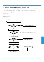
IGBT over-strong current protection diagnosis and solution

Recommended parts to prepare:

•  Faulty IGBT

•  Faulty outdoor PCB

Troubleshooting and repair:

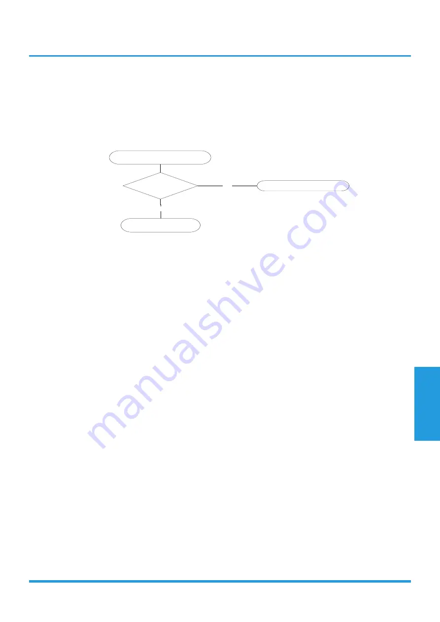
Shut off the power supply and 

turn it on 2 minutes later. 

Is it still displaying 

the error code? 

YES

Replace the outdoor main 

PCB. 

The unit is operating normally. 

NO

Summary of Contents for MISSION2 3D INVERTER Series

Page 1: ...MISSION2 3D INVERTER SERIES SM_MISSION2 GA _60R410A_3D INVERTER_US_NA_171121 2017 SERVICE MANUAL...

Page 2: ......

Page 3: ...e and Disassembly 21 1 Maintenance 2 Disassembly 5 Troubleshooting 72 1 Safety Caution 2 General Troubleshooting 3 Error Diagnosis and Troubleshooting Without Error Code 4 Quick Maintenance by Error C...

Page 4: ......

Page 5: ...Contents 1 In Case of Accidents or Emergency 2 2 Pre Installation 2 3 Operation and Maintenance 2 Safety Precautions...

Page 6: ...electri cal work For more information contact your dealer seller or an authorized Midea service center CAUTION While unpacking be careful of sharp edges around the unit as well as the edges of the fi...

Page 7: ...Contents 1 Model Reference 4 2 Electrical Wiring Diagrams 5 2 1 Indoor Unit 5 2 2 Outdoor Unit 6 Specifications...

Page 8: ...ipment Indoor Unit Model Outdoor Unit Model Capacity Btu Power Supply MSMBB 09HRFN1 BT0W MOBA01 09HFN1 BT0W 9k 115V 60Hz 1Phase MSMBB 12HRFN1 BT0W MOB01 12HFN1 BT0W 12k MSMBB 09HRFN1 MW0W MOB01 09HFN1...

Page 9: ...ve and Negative Ion Generator CAP Capacitor PLASMA Electronic Dust Collector L LIVE N NEUTRAL Heater The Electric Heating Belt of Indoor Unit T1 Indoor Room Temperature T2 Coil Temperature of Indoor H...

Page 10: ...t FAN DC FAN Direct Current FAN CT1 AC Current Detector COMP Compressor T3 Coil Temperature of Condenser T4 Outdoor Ambient Temperature TH Compressor Suction Temperature TP Compressor Discharge Temper...

Page 11: ...Specifications Page 7 MOB01 09HFN1 MW0W MOB01 12HFN1 MV0W MOCA01 18HFN1 MT0W...

Page 12: ...Specifications Page 8 MOD01 23HFN1 MT0W...

Page 13: ...606 C605 C601 C509 C508 C507 C506 C505 C504 C503 C412 C410 C409 C408 C405 C404 C 4 0 3 C402 C401 C322 C312 C305 C303 C302 C274 C273 C272 C271 C133 C132 C131 C130 C129 C128 C127 C126 C125 C124 C123 C12...

Page 14: ...1 C40 C50 D403 R401 R405 R406 R404 E404 D402 D404 C408 C402 E403 R407 R408 C404 C110 E409 E401 R402 C405 10 9 7 6 5 4 3 1 T401 C406 C407 D13 D14 E406 E407 E408 E502 E503 E504 DZ503 CN25 R6 R9 CN60 IC4...

Page 15: ...Specifications Page 11 PCB board of MOD01 23HFN1 MT0W...

Page 16: ...Specifications Page 12 IPM board of MOD01 23HFN1 MT0W...

Page 17: ...ng Mode 16 1 6 Heating mode 17 1 7 Auto mode 17 1 8 Drying Mode 17 1 9 Forced Operation Function 18 1 10 Timer Function 18 1 11 Sleep Function 18 1 12 Auto Restart Function 18 1 13 Refrigerant Leakage...

Page 18: ...Contents 1 18 Silence Optional 19 1 19 Electrical energy consumption control function Optional 19 1 20 Information Inquiry 19 Product Features...

Page 19: ...ng error code is displayed on the indoor unit and the unit ceases operation Indoor fan delayed operation When the unit starts the louver is automatically activated and the indoor fan will operate afte...

Page 20: ...requency is more than test frequency When compressor running frequency is equal to test frequency T4 is more than 15 C or no T4 or T4 fault Change setting temperature Turbo or sleep function on off Va...

Page 21: ...increases to 80 When T1 Tsc is lower than or equal to 3 C fan speed increases to 100 1 6 3 Outdoor Fan Control The outdoor unit will be run at different fan speed according to T4 and compressor runnin...

Page 22: ...emperature rises 1 C to not higher than 30 C every hour After 2 hours the temperature stops rising and the indoor fan is fixed at low speed When heating the temperature decreases 1 C to not lower than...

Page 23: ...remote control makes it necessary not from the unit s temperature setting If the unit does not receive a signal for 7 minutes or you press Follow Me the function turns off The unit regulates temperatu...

Page 24: ...uency Actual frequency Tr Actual Frequency Compressor current dL N A Outdoor AC voltage Uo N A Indoor capacity test Sn N A Reserve Running mode Outdoor fan speed Pr Outdoor fan speed EXV opening angle...

Page 25: ...ce 22 1 1 First Time Installation Check 22 1 2 Refrigerant Recharge 24 1 3 Re Installation 25 1 3 1 Indoor Unit 25 1 3 2 Outdoor Unit 27 2 Disassembly 29 2 1 Indoor Unit 29 2 2 Outdoor Unit 46 Mainten...

Page 26: ...event air and moisture from affecting the air conditioner s performance the indoor unit as well as the pipes between the indoor and outdoor unit must be be leak tested and evacuated Leak test soap wat...

Page 27: ...evacuating for an additional 20 minutes If the pressure does not achieve 0 1 MPa 14 5 Psi after 50 minutes check for leakage If the pressure successfully reaches 0 1 MPa 14 5 Psi fully close the Hand...

Page 28: ...lve at the bottom of the cylinder If the refrigerant is R410A invert the cylinder to ensure a complete liquid charge 4 Partially open the Handle Lo manifold valve 5 Open the valve at the bottom of the...

Page 29: ...3 way valve s gas service port 3 Open the Handle Lo manifold valve to purge air from the charge hose for 5 seconds and then close it quickly 4 Close the 2 way valve 5 Operate the air conditioner in c...

Page 30: ...meter indicates 0 1 MPa 14 5 Psi If the meter does not indicate 0 1 MPa 14 5 Psi after 30 minutes continue evacuating for an additional 20 minutes If the pressure does not achieve 0 1 MPa 14 5 Psi af...

Page 31: ...uate the system for approximately one hour Confirm that the compound meter indicates 0 1 MPa 14 5Psi 4 Close the valve Low side on the charge set and turn off the vacuum pump Wait for five minutes the...

Page 32: ...invert the cylinder to ensure a complete liquid charge 4 Partially open the Handle Lo manifold valve 5 Open the valve at the bottom of the cylinder for 5 seconds to purge the air in the charge hose t...

Page 33: ...d the front panel by the tabs on the both sides and lift it see CJ_MB1_ INV_001 4 Push up the bottom of an air filter step 1 and then pull it out downwards step 2 see CJ_MB1_ INV_002 CJ_MB1_INV_001 CJ...

Page 34: ...hook towards left to open it see CJ_MB1_INV_003 6 Bend the horizontal louver lightly by both hands to loosen the hooks then remove the horizontal louver see CJ_MB1_INV_004 CJ_MB1_INV_003 CJ_MB1_INV_00...

Page 35: ...l cover see CJ_MB1_INV_005 8 Disconnect the two connectors for display board and wifi model see CJ_MB1_INV_006 9 Slid the front panel side to side to release each axis see CJ_MB1_ INV_007 CJ_MB1_INV_0...

Page 36: ...the 6 hooks of the vertical blades then pull the vertical blades rightward and remove it see CJ_MB1_ INV_008 11 Remove 1 screw of the display board see CJ_MB1_INV_009 CJ_MB1_INV_008 CJ_MB1_INV_009 No...

Page 37: ...hown in the right picture see CJ_MB1_INV_010 13 Remove 1 screw of the wifi model see CJ_MB1_INV_011 14 Rotate the wifi model in the direction shown in the right picture see CJ_ MB1_INV_012 CJ_MB1_INV_...

Page 38: ...rocedure Illustration 15 Open the screw cap and then remove the 2 screws see CJ_MB1_INV_013 16 Release the 2 hooks see CJ_MB1_ INV_014 CJ_MB1_INV_013 CJ_MB1_INV_014 Note This section is for reference...

Page 39: ...hooks in the back see CJ_MB1_INV_015 18 Pull out the panel frame while pushing the hook through a clearance between the panel frame and the heat exchanger see CJ_MB1_INV_016 CJ_MB1_INV_015 CJ_MB1_INV_...

Page 40: ...the coil temperature sensor T2 see CJ_MB1_INV_017 2 Remove one fixing screw of the electronic control box and two screws used for the ground connection see CJ_MB1_INV_017 3 An upward force is maintai...

Page 41: ...INV_019 5 Disconnect the connectors of fan motor the step motor and the T2 sensor see CJ_MB1_INV_020 6 Open the left side plate of electronic control box see CJ_MB1_INV_021 CJ_MB1_INV_019 CJ_MB1_INV_0...

Page 42: ...electronic control box see CJ_MB1_INV_022 8 Remove 1 screw to take down the power wire see CJ_MB1_INV_023 9 Remove the two connectors of the transformer see CJ_MB1_INV_024 CJ_MB1_INV_022 CJ_MB1_INV_0...

Page 43: ...long the direction indicated in right image see CJ_MB1_ INV_024 11 Pull out the electrical main board along the direction indicated in right image to remove it see CJ_MB1_ INV_025 CJ_MB1_INV_024 CJ_MB...

Page 44: ...rts before disassembling evaporator Procedure Illustration 1 Disassemble the pipe holder located at the rear of the unit see CJ_MB1_INV_026 2 Remove the 1 screws on the evaporator located at the fixed...

Page 45: ...aporator see CJ_MB1_INV_028 Remote the one screw on the evaporator located at the fixed plate see CJ_MB1_ INV_029 4 Pull out the evaporator see CJ_MB1_ INV_030 CJ_MB1_INV_028 CJ_MB1_INV_029 CJ_MB1_INV...

Page 46: ...Electrical parts and 3 Evaporator before disassembling fan motor and fan Procedure Illustration 1 Remove the two screws and remove the fixing board of the fan motor see CJ_ MB1_INV_031 2 Remove the be...

Page 47: ...age 43 Procedure Illustration 3 Remove the fixing screw see CJ_OP_ INV_020 4 Pull out the fan motor and fan assembly from the side CJ_OP_INV_021 Note This section is for reference only Actual unit app...

Page 48: ...ctrical parts refer to 1 Front panel 2 Electrical parts before disassembling step motor Procedure Illustration 1 Remove the two screws then remove the stepping motor see CJ_OP_INV_021 CJ_OP_INV_021 No...

Page 49: ...dure Illustration 1 Rotate the fixed wire clockwise indicated in right image see CJ_MB1_INV_035 2 Pull up the drain hose to remove it see CJ_MB1_INV_036 CJ_MB1_INV_035 CJ_MB1_INV_036 Note This section...

Page 50: ...power breaker 2 Remove the screws of the big handle and then remove the big handle 1 screw see CJ_B01_INV_001 3 Remove the screws of the top cover and then remove the top cover 3 screws One of the scr...

Page 51: ...ove the screws of the front panel and then remove the front panel 7 screws see CJ_B01_INV_004 6 Remove the screws of water collecting cover and then remove the water collecting cover 1 screw see CJ_B0...

Page 52: ...Page 48 Procedure Illustration 7 Remove the screws of the right panel and then remove the right panel 5 screws see CJ_B01_INV_006 CJ_B01_INV_006 Note This section is for reference only Actual unit app...

Page 53: ...e screws of the big handle and then remove the big handle 1 screw see CJ_BA01_INV_001 3 Remove the screws of the top cover and then remove the top cover 3 screws One of the screws is located underneat...

Page 54: ...t panel and then remove the front panel 7 screws see CJ_BA01_INV_003 2 Remove the screws of water collecting cover and then remove the water collecting cover 1 screw see CJ_ BA01_INV_004 CJ_BA01_INV_0...

Page 55: ...mbly Page 51 Procedure Illustration 1 Remove the screws of the right panel and then remove the right panel 5 screws see CJ_BA01_INV_005 CJ_BA01_INV_005 Note This section is for reference only Actual u...

Page 56: ...f the big handle and then remove the big handle 1 screw see CJ_CA01_INV_001 3 Remove the screws of the top cover and then remove the top cover 3 screws One of the screws is located underneath the big...

Page 57: ...emove the front panel 7 screws see CJ_CA01_INV_003 5 Remove the screws of water collecting cover and then remove the water collecting cover 1 screw see CJ_ CA01_INV_004 CJ_CA01_INV_003 CJ_CA01_INV_004...

Page 58: ...age 54 Procedure Illustration 6 Remove the screws of the right panel and then remove the right panel 7 screws see CJ_CA01_INV_005 CJ_CA01_INV_005 Note This section is for reference only Actual unit ap...

Page 59: ...he screws of the big handle and then remove the big handle 2 screws see CJ_D01_INV_001 3 Remove the screws of the top cover and then remove the top cover 4 screws Two of the screws is located undernea...

Page 60: ...front right panel and then remove the front right panel 2 screws see CJ_D01_ INV_003 2 Remove the screws of the front panel and then remove the front panel 9 screws see CJ_D01_INV_004 CJ_D01_INV_003 C...

Page 61: ...collecting cover and then remove the water collecting cover 2 screw see CJ_ D01_INV_005 2 Remove the screws of the right panel and then remove the right panel 8 screws see CJ_D01_INV_006 CJ_D01_INV_00...

Page 62: ...llustration 1 Remove the nut securing the fan with a spanner see CJ_ODU_ INV_001 2 Remove the fan 3 Remove the screws of the top cover 2 screws see CJ_ODU_INV_002 4 Unfix the hooks and then open the e...

Page 63: ...ector for fan motor from the electronic control board see CJ_ODU_INV_004 6 Remove the fixing screws of the fan motor 4 screws see CJ_ODU_INV_005 7 Remove the fan motor CJ_ODU_INV_004 CJ_ODU_INV_005 No...

Page 64: ...llustration 1 Remove the nut securing the fan with a spanner see CJ_ODU_ INV_006 2 Remove the fan 3 Unfix the hooks and then open the electronic control box cover 4 hooks see CJ_ODU_INV_007 CJ_ODU_INV...

Page 65: ...ector for fan motor from the electronic control board see CJ_ODU_INV_008 5 Remove the fixing screws of the fan motor 4 screws see CJ_ODU_INV_009 6 Remove the fan motor CJ_ODU_INV_008 CJ_ODU_INV_009 No...

Page 66: ...r see CJ_ODU_ INV_010 2 Remove the fan 3 Remove the fixing screws of the electronic control box see CJ_ODU_ INV_011 4 Unfix the hooks and then open the electronic control box cover 5 hooks see CJ_ODU_...

Page 67: ...connector for fan motor from the electronic control board see CJ_ODU_INV_013 2 Remove the fixing screws of the fan motor 4 screws see CJ_ODU_INV_014 3 Remove the fan motor CJ_ODU_INV_013 CJ_ODU_INV_0...

Page 68: ..._INV_015 2 Pull out the two blue wires connected with the four way valve CJ_ODU_ INV_015 3 Pull out connectors of the condenser coil temp sensor T3 outdoor ambient temp sensor T4 and discharge temp se...

Page 69: ...l out connectors of the condenser coil temp sensor T3 outdoor ambient temp sensor T4 and discharge temp sensor TP see CJ_ODU_INV_016 4 Disconnect the electronic expansion valve wire see Fig CJ_ODU_INV...

Page 70: ...U_ INV_016 3 Pull out connectors of the condenser coil temp sensor T3 outdoor ambient temp sensor T4 and discharge temp sensor TP see CJ_ODU_INV_016 4 Disconnect the electronic expansion valve wire se...

Page 71: ...he panel plate electrical parts and fan assembly refer to 1 Panel plate 2 Electrical parts and 3 Fan assembly before disassembling sound blanket Procedure Illustration 1 Remove the sound blanket side...

Page 72: ...al parts and fan assembly refer to 1 Panel plate 2 Electrical parts and 3 Fan assembly before disassembling four way valve Procedure Illustration 1 Heat up the brazed parts and then detach the the fou...

Page 73: ...an assembly refer to 1 Panel plate 2 Electrical parts and 3 Fan assembly before disassembling compressor Procedure Illustration 1 Remove the flange nut of terminal cover and remove the terminal cover...

Page 74: ...e bottom plate see CJ_ODU_INV_021 4 Heat up the brazed parts and then remove the the discharge pipe and the suction pipe see CJ_ODU_INV_022 5 Lift the compressor from the base pan assembly with pliers...

Page 75: ...tdoor unit communication error 87 5 4 E3 F5 Fan speed is operating outside of the normal range 89 5 5 E4 E5 F1 F2 F3 Open circuit or short circuit of temperature sensor diagnosis and solution 91 5 6 E...

Page 76: ...EEPROM parameter error diagnosis and solution 100 5 14 Zero speed protection of compressor outdoor fan or lack of phase of compressor or outdoor fan Compressor speed malfunction diagnosis and solutio...

Page 77: ...scharged before troubleshooting For other models connect discharge resistance approx 100 40W or a soldering iron plug between the positive and negative terminals of the electrolytic capacitor The term...

Page 78: ...ad current protection Page 83 F1 Outdoor ambient temperature sensor T4 open circuit or short circuit Page 80 F2 Condenser coil temperature sensor T3 is in open circuit or has short circuited Page 80 F...

Page 79: ...n When in low ambient cooling mode it flashes 4 times then stops 4 seconds LED2 Red color and LED3 Green color refer to the following table LED2 Red LED3 Green Error Information Solution on off Normal...

Page 80: ...LED4 Red LED3 Green Error Information Solution on off Normal operation Normal off on Normal standby Normal Flash OFF Compressor speed malfunction or outdoor fan speed malfunction Page 72 85 Flash On C...

Page 81: ...field maintenance Problem Solution 1 Unit will not start Page 79 80 2 The power switch is on but fans will not start Page 79 80 3 The temperature on the display board cannot be set Page 79 80 4 Unit i...

Page 82: ...82 5 Condenser Outdoor fan will not start Page 81 82 6 Unit runs but shortly stops Page 81 82 7 Compressor short cycles due to overload Page 81 82 8 High discharge pressure Page 81 82 9 Low discharge...

Page 83: ...utdoor fan motor x x x X x x x x x Temperature sensor x x x x x x T2 Sensor x x x x x x x x Additional refrigerant x x x x x x x x x Compressor x x x x x x x x IPM board x x x x x x x x x Outdoor unit...

Page 84: ...g frequently Unit will not start The power switch is on but fans will not start The temperature on the display board cannot be set Unit is on but the wind is not cold hot Unit runs but shortly stops T...

Page 85: ...or outlet of either unit is blocked Interference from cell phone towers and remote boosters Shipping plates remain attached Check heat load Tighten bolts or screws Close all the windows and doors Rem...

Page 86: ...t Condenser Outdoor fan will not start Unit runs but shortly stops Compressor short cycles due to overload High discharge pressure Low discharge pressure High suction pressure Low suction pressure Uni...

Page 87: ...ulb Heavy load condition Loosen hold down bolts and or screws Shipping plates remain attached Poor choices of capacity Contact of piping with other piping or external plate Replace the compressor Leak...

Page 88: ...T1 sensor Indoor coil temp T2 sensor Outdoor coil temp T3 sensor Outdoor ambient temp T4 sensor Compressor discharge temp Tp sensor Measure the resistance value of each winding by using the multi mete...

Page 89: ...acity electrolytic capacitors discharge completely and dismount the IPM Use a digital tester to measure the resistance between P and UVWN UVW and N Digital tester Normal resistance value Digital teste...

Page 90: ...n it on 2 minutes later Is it still displaying the error code The unit is operating normally NO If the EEPROM chip is welded on main PCB replace the main PCB directly Otherwise check if the EEPROM chi...

Page 91: ...mally NO Measure Vs Vs is the voltage between S and N of outdoor unit Red pan S Black pan N YES Is the voltage moving alternately between Positive and negative Check the outdoor wiring connection Is i...

Page 92: ...running the voltage is moving alternately as positive values and negative values If the outdoor unit has malfunction the voltage has always been the positive value While if the indoor unit has malfunc...

Page 93: ...lay the failure F5 Recommended parts to prepare Wiring mistake Faulty fan assembly Faulty fan motor Faulty PCB Troubleshooting and repair YES Power off then restart the unit after 2 minutes Is it with...

Page 94: ...t voltage 220 240V No Color Signal Voltage 1 Red Vs Vm 280V 380V 2 3 Black GND 0V 4 White Vcc 14 18 5V 5 Yellow Vsp 0 5 6V 6 Blue FG 14 18 5V 2 Outdoor DC Fan Motor control chip is in outdoor PCB Powe...

Page 95: ...than 4 94V the LED will display the failure Recommended parts to prepare Wiring mistake Faulty sensor Faulty PCB Troubleshooting and repair Check the connection between temperature sensor and PCB Repl...

Page 96: ...stake PCB faulty Display board malfunction Troubleshooting and repair Power off then restart the unit 2 minutes later Is it still displaying the error code The unit operates normally NO Check the wiri...

Page 97: ...EC and AC will turn off Recommended parts to prepare Faulty T2 sensor Faulty indoor PCB System problems such as leakage or blockages Power off then restart the unit 2 minutes later Are any leakages p...

Page 98: ...malfunction Troubleshooting and repair Check the power supply Do any exist Are they within acceptable parameters Are they properly connected Is it in working order Replace the outdoor unit Is it in w...

Page 99: ...bleshooting and repair Check the wiring between PCB and compressor Does an error exist Ensure proper connections or replace the wires and connectors YES Check the IPM NO Is it in working order Replace...

Page 100: ...oubleshooting and repair Check the power supply Is it in working order Turn off the unit NO Check the connections and wires YES Are they in working order Ensure proper connections or replace the wires...

Page 101: ...Troubleshooting Page 97 Remark Measure the DC voltage between P and N port The normal value should be around 310V...

Page 102: ...of IPM module is higher than limited value the LED displays this failure code Recommended parts to prepare Faulty PCB Connection problems Troubleshooting and repair Check the fastening screws on the...

Page 103: ...ssembly Compressor malfunction Faulty outdoor PCB Troubleshooting and repair Check the wiring between the PCB and compressor Is it improperly wired Ensure proper connections or replace the wires and c...

Page 104: ...utdoor PCB main chip does not receive feedback from compressor driven EEPROM chip Recommended parts to prepare Outdoor PCB Troubleshooting and repair Shut off the power supply and turn it on 2 minutes...

Page 105: ...properly wired Ensure proper connections or replace the wires and connectors Ensure proper connections or replace the wires and connectors YES NO Check the outdoor fan and the outdoor unit ventilation...

Page 106: ...nd compressor driven chip diagnosis and solution Recommended parts to prepare Faulty PCB Troubleshooting and repair Shut off the power supply and turn it on 2 minutes later Is it still displaying the...

Page 107: ...gnosis and solution Recommended parts to prepare Faulty IGBT Faulty outdoor PCB Troubleshooting and repair Shut off the power supply and turn it on 2 minutes later Is it still displaying the error cod...

Page 108: ...ontents i Temperature Sensor Resistance Value Table for T1 T2 T3 and T4 C K 105 ii Temperature Sensor Resistance Value Table for TP C K 106 iii T F 9 T C 5 107 iv Pressure On Service Port 108 Appendix...

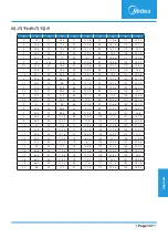
Page 109: ...71 1 29078 117 243 0 38991 2 28 39 8239 38 100 5 62961 78 172 1 25423 118 244 0 37956 1 30 37 1988 39 102 5 39689 79 174 1 2133 119 246 0 36954 0 32 35 2024 40 104 5 17519 80 176 1 17393 120 248 0 359...

Page 110: ...78 75 167 8 084 115 239 2 422 4 25 222 8 36 97 34 32 76 169 7 82 116 241 2 357 3 27 211 4 37 99 32 94 77 171 7 566 117 243 2 294 2 28 200 7 38 100 31 62 78 172 7 321 118 244 2 233 1 30 190 5 39 102 30...

Page 111: ...201 2 125 257 4 39 2 33 91 4 64 147 2 95 203 126 258 8 4 5 40 1 34 93 2 65 149 96 204 8 127 260 6 5 41 35 95 66 150 8 97 206 6 128 262 4 6 42 8 36 96 8 67 152 6 98 208 4 129 264 2 7 44 6 37 98 6 68 15...

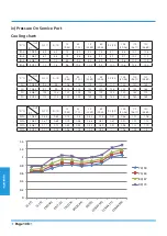
Page 112: ...9 44 95 35 105 40 56 115 46 11 120 48 89 PSI 70 59 93 94 106 116 119 113 117 125 147 154 PSI 75 63 97 99 115 125 124 120 126 132 155 162 PSI 80 67 103 104 123 138 135 129 132 140 162 173 PSI 90 73 112...

Page 113: ...T 57 53 13 89 11 67 47 43 8 33 6 11 37 33 2 78 0 56 27 23 2 78 5 17 13 8 33 10 56 0 2 17 19 17 18 27 28 PSI 55 439 413 367 330 302 268 239 PSI 65 471 435 386 368 339 297 276 PSI 75 489 457 403 381 362...

Reviews: