background image

  MCAC-KTSM-2007-2   


  Introduction 

Introduction                                                                                                                                                                                                      1 

Introduction 

Fan coil unit is a kind of compound device which assemble fan and surface-type coil heating-exchanger 
together. Fan coil with fresh air supply system is a main type of center air-conditioner system, so it is an 
important component of AC devices. Fan coil has horizontal type, vertical type, etc. A cooling (heating) 
supply system usually consists of fan coil terminals and chilled water system (heated water system).   


Midea

®

 commercial AC fan coil is designed and manufactured on the base of advanced technology, and 

utilize qualified galvanized iron as material. Due to its supper-thin design, it has such advantages: beautiful 
outlook, space saving, easy installation, etc. And the most obvious advantage is that it can decrease the 
outlet air Temp-dif

ference as low as possible to make room more comfortable, as well as don’t decrease 

cooling capacity output. For the large air flow volume design, it can increase room ventilation frequency, 
supply more flesh air, and balance room temperature distribution. Benefiting from adoption of advanced 
material and technology, it can effectively decrease the running noise and keep running smoothly. With the 
advantages above, it can be widely applied in market, hospital, office building, hotel airport, etc. 

Summary of Contents for MKA-1200

Page 1: ...Operation Maintenance Manual MKA MKB MKC MKT MKT2 200CFM 1500CFM 50Hz 60Hz Fan Coil Unit Cassette and Ceiling Concealed Series...

Page 2: ...Content MCAC KTSM 2007 2 i Content Introduction 1 Part 1 General Information 2 Part 2 Indoor Unit 7 Part 3 Installation 127...

Page 3: ...vanced technology and utilize qualified galvanized iron as material Due to its supper thin design it has such advantages beautiful outlook space saving easy installation etc And the most obvious advan...

Page 4: ...General information MCAC KTSM 2007 2 2 General Information Part 1 General Information 1 Model Names of Fan Coil 3 2 External Appearance 4 3 Nomenclature 5 4 Features 6...

Page 5: ...600 Cassette type fan coil MKA 750 MKA 850 MKA 950 MKA 1200 MKA 1500 MKT2 H 200 2 Rows Duct type fan coil MKT2 H 300 MKT2 H 400 MKT2 H 500 MKT2 H 600 MKT2 H 800 MKT2 H 1000 MKT2 H 1200 MKT2 H 1400 MKT...

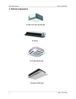
Page 6: ...External Appearance MCAC KTSM 2007 2 4 General Information 2 External Appearance Compact four way cassette type Duct type Four way cassette type One way cassette type...

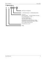
Page 7: ...ter Fan coil unit 12Pa Static Pressure H 30Pa Static Pressure F3 Concealed Flood stand Type F2 Exposed Flood stand Type below air intake Type Code T2 2nd Generation Duct Type A 4 Way Cassette B 4 Way...

Page 8: ...it capacitor motor Copper tube aluminum fin coils Hydrophilic aluminum fin coils coated optional Unit constructed by electrostatic galvanized sheet providing maximum protection against corrosion Heavy...

Page 9: ...MCAC KTSM 2007 2 Indoor Units Indoor Units 7 Part 2 Indoor Units Four Way Cassette Type 6 Compact Four Way Cassette Type 25 Duct Type 38 One Way Cassette Type 106...

Page 10: ...sette Type MCAC KTSM 2007 2 8 Indoor Units Four Way Cassette Type 1 Features 9 2 Specification 10 3 Dimensions 12 4 Service Space 13 5 Wiring Diagrams 14 6 Capacity Tables 15 7 Sound Levels 22 8 Explo...

Page 11: ...natural and comfortable environment 2 Efficient cooling Equal fast and wide range cooling 3 The adoption of the most advanced 3 Dimensional Screw fan Reduces the air resistance passing through Smoothe...

Page 12: ...eed fan motor Number 1 Model YDK56 6 YDK55 6 Input W 144 144 128 120 Capacitor uF 3 5 3 5 3 5 3 5 Indoor unit Dimension W H D mm 840 310 840 840 240 840 Packing W H D mm 1020 410 930 1020 330 930 Net...

Page 13: ...45 Water flow LPH 2388 1928 Water resistance kPa 46 44 Indoor Coil Number of rows 2 Tube pitch a x row pitch b mm 25 4 22 Fin spacing mm 1 3 Fin type Hydrophilic aluminum Tube outside dia and type mm...

Page 14: ...Cassette Type 3 Dimensions MKA 600 MKA 750 Gas side E parts box Liquid side 4 install hanger Drain hole Pump inspect hole MKA 850 MKA 950 MKA 1200 MKA 1500 310 4 install hanger Gas side liquid side E...

Page 15: ...MCAC KTSM 2007 2 Service Space Four Way Cassette Type 13 4 Service Spaces MKA 600 MKA 750 MKA 850 MKA 950 MKA 1200 MKA 1500...

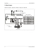
Page 16: ...DRAWING POWER 220V 240V 50Hz FAN1 BE N N1 L1 PUMP Y G CAP1 Y G XS1 XS2 Rt3 XT1 XP1 XP2 T4 K3 Rt2 FAN1 2CON10 DISPLAY CAP1 CONNECTORS 6 WAY TERMINAL TRANSFORMER PIPE TEMPERATURE SENSOR PUMP WATER PUMP...

Page 17: ...25 84 4 3654 4618 3815 5172 3966 5753 4181 6039 4261 6959 8 10 13 5 3028 3082 3136 3475 3234 3877 3421 4083 3430 4717 15 30 4 3243 3627 3368 4091 3502 4574 3698 4815 3743 5574 20 54 3386 3975 3529 44...

Page 18: ...4097 5110 4264 5723 4440 6353 4671 6679 4759 7684 8 15 11 9 3507 3690 3643 4161 3762 4639 3977 4886 4001 5644 20 21 2 3675 4105 3826 4639 3970 5181 4193 5539 4241 6321 25 33 1 3810 4432 3970 5006 4129...

Page 19: ...4748 5921 4942 6632 5145 7362 5413 7740 5514 8904 8 15 11 9 4064 4277 4221 4822 4360 5376 4609 5662 4637 6540 20 21 2 4258 4757 4434 5376 4600 6004 4858 6419 4914 7325 25 33 1 4415 5136 4600 5801 4785...

Page 20: ...7 5304 6614 5520 7408 5747 8224 6047 8646 6160 9946 8 15 11 9 4540 4777 4716 5386 4870 6005 5148 6325 5180 7305 20 21 2 4757 5314 4953 6005 5138 6707 5428 7171 5490 8182 25 33 1 4933 5737 5138 6480 53...

Page 21: ...1 40 46 5 6683 8328 6972 9316 7243 10348 7628 10873 7768 12509 8 25 18 2 5983 6613 6220 7471 6456 8345 6814 8791 6893 10174 32 29 8 6132 7007 6395 7908 6639 8844 7016 9316 7121 10795 35 35 6 6255 7304...

Page 22: ...74 40 46 5 7842 9771 8180 10931 8498 12142 8950 12758 9114 14677 8 25 18 2 7020 7759 7298 8765 7575 9792 7995 10315 8088 11937 32 29 8 7195 8221 7503 9278 7790 10377 8232 10931 8355 12666 35 35 6 7339...

Page 23: ...9 9525 10811 13382 15961 MKA 950 15 11 9 5869 7199 8537 9868 11180 13830 16498 20 21 2 6174 7574 8971 10383 11754 14553 17351 25 33 1 6366 7820 9270 10716 12139 15025 17920 30 47 7 6518 7997 9473 1095...

Page 24: ...Sound Levels MCAC KTSM 2007 2 22 Four Way Cassette Type 7 Sound Levels TYPE MKA 600 MKA 750 MKA 850 MKA 950 MKA 1200 MKA 1500 Noise dB A 41 41 44 44 45 45 FOUR WAY CASSETTE TYPE Microphone 1 0m...

Page 25: ...embly 1 27 holder pump 1 3 E Parts Box Cover1 1 28 Water trying board 1 4 Capacity 1 29 Panel Assembly 4 5 E Parts Box Assembly 1 30 Cover installing 1 6 E Parts Box Cover2 1 31 Swing motor 4 7 Transf...

Page 26: ...tor Base assembly 1 41 Cover control box 1 16 Base Pan assembly 1 42 Panel 1 Wire clamp board 1 43 Back board Air out 1 1 17 Sealing board pipe out 1 44 Back board Air out 2 1 18 Remoter 1 45 Back boa...

Page 27: ...Way Cassette Type Compact Four Way Cassette Type 25 Compact Four Way Cassette Type 1 Features 26 2 Specification 27 3 Dimensions 28 4 Service Space 29 5 Wiring Diagrams 30 6 Capacity Tables 31 7 Sound...

Page 28: ...the air resistance passing through Smoothes the air flow Makes air speed distribution to the heat exchange uniform 4 Fresh air makes life healthier and more comfortable 4 Improvement for easy install...

Page 29: ...otor Type Low noise 3 speed fan motor Number 1 Model YDK45 4F Input W 30 45 55 70 Capacitor uF 1 1 5 2 3 Indoor unit Dimension W H D mm 580 254 580 Packing W H D mm 750 340 750 Net Gross weight kg 21...

Page 30: ...ette Type 3 Dimensions MKB 300 MKB 400 MKB 450 MKB 500 5 8 0 B o d y 67 600 Ceiling hole 650 Panel 401 Hook location 611 Hook location 580 Body 422 28 5 600 Ceiling hole 650 Panel Drain side and Tubin...

Page 31: ...MCAC KTSM 2007 2 Service Space Compact Four Way Cassette Type 29 4 Service Space...

Page 32: ...Wring Diagram MCAC KTSM 2007 2 30 Compact Four Way Cassette 5 Wiring Diagram CN7 CN11 CN10 CN2 CN19 CN1 CN5 CN12 CN4 CN8 CN9 CN17 TO CONTROLER 5 CN3 2 Y BL...

Page 33: ...2775 12 18 2 1592 1968 1655 2336 1724 2608 1815 2816 1843 2955 8 6 4 6 1349 1377 1398 1551 1446 1731 1530 1822 1530 2107 8 8 1 1419 1558 1474 1753 1530 1961 1609 2061 1634 2392 10 12 7 1467 1676 1530...

Page 34: ...8 2 1927 2382 2003 2828 2087 3156 2197 3409 2230 3577 8 6 4 6 1633 1667 1692 1877 1751 2096 1852 2205 1852 2550 8 8 1 1717 1885 1784 2121 1852 2374 1953 2500 1978 2895 10 12 7 1776 2028 1852 2298 1927...

Page 35: ...8 2 2473 3125 2575 3273 2683 3474 2823 3750 2885 4312 8 6 4 6 2032 2047 2102 2311 2172 2575 2303 2707 2296 3126 8 8 1 2179 2435 2272 2746 2358 3072 2490 3234 2513 3747 10 12 7 2272 2668 2373 3009 2474...

Page 36: ...4 4 2287 2556 2385 2881 2474 3223 2612 3394 2637 3931 8 10 13 5 2385 2800 2490 3158 2596 3540 2735 3727 2783 4330 15 30 4 2458 2979 2572 3369 2686 3776 2832 3727 2897 4297 20 54 2035 2035 2116 2189 21...

Page 37: ...MCAC KTSM 2007 2 Sound Levels Compact Four Way Cassette Type 35 7 Sound Levels TYPE MKB 300 MKB 400 MKB 450 MKB 600 Noise dB A 38 39 40 41 FOUR WAY CASSETTE TYPE Microphone 1 0m...

Page 38: ...1 26 3 Switch air inlet grille 2 3 Stopper Water Drain 1 26 4 Filter 1 5 Evaporator Fixture Board Assembly 1 26 5 Control box 1 6 Drain Pump 1 26 6 LED holder 1 7 Liquid Position Sensor Assembly 1 26...

Page 39: ...Inlet pipe evaporator 1 26 15 Install cover I 1 17 Outlet pipe evaporator 1 27 Remoter 1 18 Wire crossing board 1 29 E control Assembly 1 19 Fan 1 29 1 Control Box 1 20 Fan Motor 1 29 2 Rubber wire c...

Page 40: ...stallation of MKA MCAC KTSM 2007 2 142 The Installation of MKA The Installation of MKA 1 Before Installation 143 2 Install the Main Body 144 3 Install the Panel 146 4 Install the Drain Pipe 148 5 Wiri...

Page 41: ...TSM 2007 2 Before Installation The Installation of MKA 143 1 Before Installation Please check whether the accessories are of full scope If there are some fittings free from use please restore them car...

Page 42: ...nd then cut off the unnecessary part If the ceiling is extremely high please determine the length of the installation hook according to facts Cut the installation hook open in the middle position and...

Page 43: ...will not become loose because of concrete shrinking b After installing the body please fasten the installation paper board onto the air conditioner with bolts M6 16 to determine in advance the sizes...

Page 44: ...he panel in the direction of the arrow in Chart12 slightly to fit the panel s center to the center of the ceiling s opening Guarantee that hooks of four corners are fixed well e Keep fastening the scr...

Page 45: ...MCAC KTSM 2007 2 Install The Panel The Installation of MKA 147...

Page 46: ...ent the body from being pulled Meanwhile one support point should be set every 1 1 5m to prevent the drainpipe from yielding Refer to Chart 17 b Or you can tie the drainpipe with the connecting pipe t...

Page 47: ...hing is ok If the drain hose is located unreasonable water overflow will cause the Alarm indicator lamp flashing For both cooling and heating type or cooling only type even the water leak out from the...

Page 48: ...ational wiring regulation 4 Be sure to locate the power wiring and the signal wiring well to avoid cross disturbance and their contact with connecting pipe or stop valve body 5 The wiring 5 core shiel...

Page 49: ...TSM 2007 2 The Installation of MKB The Installation of MKB 151 The Installation of MKB 1 Before Installation 152 2 Install the Main Body 153 3 Install the Panel 155 4 Install the Drain Pipe 158 5 Wiri...

Page 50: ...tallation Please check whether the accessories are of full scope If there are some fittings free from use please restore them carefully Select the location Install the connecting pipe Install the indo...

Page 51: ...osition of installation hooks according to the hook holes on the installation board Drill four holes of 12mm 50 55mm deep at the selected positions on the ceiling Then embed the expansible hooks fitti...

Page 52: ...k into the ceiling for 10 12mm Refer to chart5 Locate the air conditioner firmly by wrenching the nuts after having adjusted the body s position well B New built houses and ceilings a In the case of n...

Page 53: ...center to the center of the ceiling s opening Guarantee that hooks of four corners are fixed well f Keep fastening the screws under the panel hooks until the thickness of the sponge between the body a...

Page 54: ...over c Bind the connecting pipe and the cables together tightly with binding tapes Do not let air in which will cause water leakage by condensation d Pass the bound connecting pipe through the wall co...

Page 55: ...in general 3 Then open the stem of stop valves of the outdoor unit to make the refrigerant pipe connecting the indoor unit with the outdoor unit in fluent flow 4 be sure of no leakage by checking it w...

Page 56: ...fer to Chart 24 b Or you can tie the drainpipe with the connecting pipe to fix it Refer to Chart 24 c In the case of prolonged drainpipe you had better tighten its indoor part with a protection tube t...

Page 57: ...itioner for there minutes check if everything is ok If the drain hose is located unreasonable water overflow will cause the Alarm indicator lamp flashing For both cooling and heating type or cooling o...

Page 58: ...tween the signal receiving board and the wire controller is not more than 2m Be sure to prolong it with wiring of the same type and proper length if necessary Generally do not twist two wiring togethe...

Page 59: ...al management system Standard ISO 14001 certification Certificate Numer CC 1417 GD Midea Air conditioning Equipment Add Penglai Road Beijiao Shunde Foshan Guangdong China Tel 86 757 26338538 Fax 86 75...

Reviews: