background image


1

1. Precaution 

1.1  Safety Precaution 


To prevent injury to the user or other people 

and property damage, the following instructions 

must be followed. 


Incorrect operation due to ignoring 

instruction will cause harm or damage.   


Before service unit, be sure to read this 

service manual at first. 


1.2  Warning 


Installation 


Do not use a defective or underrated circuit 

breaker. Use this appliance on a dedicated 

circuit. 

There is risk of fire or electric shock. 


For electrical work, contact the dealer, seller, 

a qualified electrician, or an Authorized service 

center. 

Do not disassemble or repair the product, there is 
risk of fire or electric shock. 


Always ground the product. 

There is risk of fire or electric shock. 


Install the panel and the cover of control 

box securely. 

There is risk of fire of electric shock. 


Always install a dedicated circuit and 

breaker. 

Improper wiring or installation may cause fore or 
electric shock. 


Use the correctly rated breaker of fuse. 

There is risk of fire or electric shock. 


Do not modify or extend the power cable. 

There is risk of fire or electric shock. 


Do not install, remove, or reinstall the unit 

by yourself (customer). 

There is risk of fire, electric shock, explosion, or 
injury. 


Be caution when unpacking and installing 

the product. 

Sharp edges could cause injury, be especially 
careful of the case edges and the fins on the 
condenser and evaporator. 


For installation, always contact the dealer or 

an Authorized service center. 

There is risk of fire, electric shock, explosion, or 
injury. 


Do not install the product on a defective 

installation stand. 

It may cause injury, accident, or damage to the 
product. 


Be sure the installation area does not 

deteriorate with age. 

If the base collapses, the air conditioner could fall 
with it, causing property damage, product failure, 
and personal injury. 


Do not let the air conditioner run for a long 

time when the humidity is very high and a door 

or a window is left open. 

Moisture may condense and wet or damage 
furniture. 


Take care to ensure that power cable could 

not be pulled out or damaged during operation. 

There is risk of fire or electric shock. 


Do not place anything on the power cable. 

There is risk of fire or electric shock. 


Do not plug or unplug the power supply 

plug during operation. 

There is risk of fire or electric shock. 


Do not touch (operation) the product with 

wet hands. 

There is risk of fire or electric shock. 


Do not place a heater or other appliance 

near the power cable. 

There is risk of fire and electric shock. 


Do not allow water to run into electric parts. 

It may cause fire, failure of the product, or electric 
shock. 


Do not store or use flammable gas or 

combustible near the product. 

There is risk of fire or failure of product. 


Do not use the product in a tightly closed 

space for a long time. 

Oxygen deficiency could occur. 


When flammable gas leaks, turn off the gas 

and open a window for ventilation before turn the 

product on. 

Do not use the telephone or turn switches on or off. 
There is risk of explosion or fire. 


If strange sounds, or small or smoke comes 

from product. Turn the breaker off or disconnect 

the power supply cable. 

There is risk of electric shock or fire. 


Stop operation and close the window in 

storm or hurricane. If possible, remove the 

product from the window before the hurricane 

Summary of Contents for MOF-24HDN1-QC2W

Page 1: ...SERVICE MANUAL MIDEA AIRCONDITIONER DC INVERTER SPLIT WALL MOUNTED TYPE MSR1 24HRDN1 QC2W V1 0 Mar 2010...

Page 2: ...e installation 13 7 6 Re air purging Re installation 14 7 7 Balance refrigerant of the 2 way 3 way valves 15 7 8 Evacuation 16 7 9 Gas charging 17 8 Electronic function 18 8 1 Abbreviation 18 8 2 Disp...

Page 3: ...a defective installation stand It may cause injury accident or damage to the product Be sure the installation area does not deteriorate with age If the base collapses the air conditioner could fall wi...

Page 4: ...directly It may cause corrosion on the product Corrosion particularly on the condenser and evaporator fins could cause product malfunction or inefficient operation Operational Do not expose the skin d...

Page 5: ...3 your skin or clothes wash it well with clean Do not use the remote of the batteries have leaked The chemical in batteries could cause burns or other health hazards...

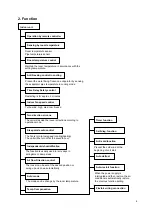
Page 6: ...direction according to operation mode Turbo wind high med low breeze Restarting is for approx 3 minutes Prevent the water being frozen on evaporator by sensing the evaporator pipe temperature in cooli...

Page 7: ...ency at operation mode Hydrophilic aluminum fin It is only operated in the heating operation mode except defrosting operation Anti rust cabinet Valve protection cover 4 way valve control Made from ele...

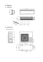
Page 8: ...6 3 Dimension 3 1 Indoor Unit 3 2 Outdoor Unit MOF 24HDN1 QC2W Dimension Model W H D 24k 1030 313 221...

Page 9: ...45 41 Indoor unit Dimension W H D mm 1030 313 221 Packing W H D mm 1135 435 315 Net Gross weight Kg 14 19 Outdoor fan motor Model YDK55 6G Brand Welling Input W 103 76 Capacitor uF 2 5 Speed r min 840...

Page 10: ...8 5 Refrigerant cycle diagram...

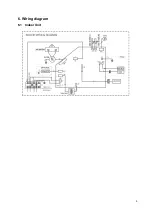
Page 11: ...9 6 Wiring diagram 6 1 Indoor Unit...

Page 12: ...10 6 2 Outdoor Unit...

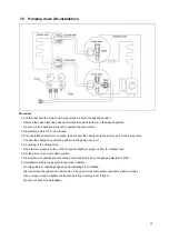
Page 13: ...16 0 3 8 9 52 5 10 25 40 Caution Capacity is based on standard length and maximum allowance length is base of reliability Oil trap should be installed per 5 7 meters 7 4 Air purging of the piping and...

Page 14: ...and then wait for one minute 5 Use torque wrench to tighten the service port cap to a torque of 1 8 kgf m 18N m 6 Set the 3 way valve to the opened position 7 Mounted the valve stem nuts to the 2 way...

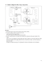
Page 15: ...hose with the push pin to the gas service port 5 Air purging of the charge hose Open the low pressure valve on the charge set slightly to purge air from the charge hose 6 Set the 2 way valve to the cl...

Page 16: ...te repeat 3 times After purging the air use a torque wrench to tighten the flare nut to on the 2 way valve 4 Check the gas leakage Check the flare connections for gas leakage 5 Discharge the refrigera...

Page 17: ...ice port 3 Open the valves Low side on the charge set and discharge the refrigerant until the gauge indicates 0 05 to 0 1Mpa If there is no air in the refrigeration cycle the pressure when the air con...

Page 18: ...ved toward 0 1 Mpa 76 cmHg vacuum of 4 mmHg or less 3 Close the valve Low side on the charge set turn off the vacuum pump and confirm that the gauge needle does not move approximately 5 minutes after...

Page 19: ...fied amount of refrigerant if can be charged with a little at a time approximately 150g each time0 while operating the air conditioner in the cooling cycle however one time is not sufficient wait appr...

Page 20: ...8 2 2 LED display control function Pressing LED display button on remote controller will turn off all displays on indoor unit while pressing once again all displays will resume 8 3 Protection 8 3 1 Pr...

Page 21: ...cable will work 2 Preheating mode A weak current flows through the coil of compressor from the wiring terminal of compressor then the compressor is heated without operation 3 Preheating release condit...

Page 22: ...ler 6 times or more within 10 seconds make sure indoor unit receives these signals the machine will turn into rating capacity test mode the buzzer will make a di sound for 2 seconds continuously Also...

Page 23: ...changed The horizontal angle is the same as in cooling mode 8 6 2 Room overlow temperature protection In drying mode if room temperature is lower than 10 compressor will stop and not resume until roo...

Page 24: ...ed 8 7 2 Indoor fan speed can be set as high medium low or auto grade but anti cold wind function is preferential Auto fan action in heating mode 8 7 3 After start the operation frequency of compresso...

Page 25: ...ion 1 if the two items are satisfied then judges if T2 has descended for more than 5 if it has the machine starts defrosting or continues to judge T2 and will not defrost until T2 drops more than 5 Co...

Page 26: ...rating capacity test mode 2 The machine will quit from the rating capacity test mode if running for 5 hours or changing fan speed or setting temperature 8 7 9 Turbo function in heating mode Elevate c...

Page 27: ...essing the touch button continuously the unit will be turned off 8 9 3 In forced operation mode all general protections is available 8 9 4 In forced cooling mode the unit will run with fixed frequency...

Page 28: ...follow 1 After pressing ECONOMIC or SLEEP button on controller the machine will turn into sleep mode 2 When cooling the setting temperature rises 1 be lower than 30 every one hour 2 hour later the ris...

Page 29: ...pacitors in PCB and relative circuit in outdoor unit even shut down the power supply electricity power still are kept in capacitors do not forget to discharge the electricity power in capacitor Electr...

Page 30: ...munication protection E5 Open or short circuit of outdoor temperature sensor E6 Open or short circuit of indoor temperature sensor P0 Inverter module over strong current protection P1 Over voltage or...

Page 31: ...between indoor and outdoor unit Is the connection of L N S and GND good Is the GND connection on outdoor PCB good NO NO Reconnect and retest again Is the LED4 red on outdoor PCB bright and LED1 yello...

Page 32: ...nd compressor good Repair or correct the connector or connection Replace the outdoor PCB and then repower on Is the failure cleared NO YES Check the compressor NO Is the indoor temperature and evapora...

Page 33: ...ressor is it right YES Replace inverter compressor Reconnect and retry NO NO YES Does compressor operate Is the connection good Is refrigerant circulation volume normal NO NO Charge refrigerant Is abn...

Page 34: ...value of each winding by using the multi meter 9 3 2 Outdoor Fan Motor Model YDK55 6G Measure the resistance value of each winding by using the multi meter Position Resistance Value Blue Red 0 95 20 B...

Page 35: ...or Measure the resistance value of each winding by using the multi meter Some frequently used R T data for T1 T2 T3 and T4 sensor Temperature 5 10 15 20 25 30 40 50 60 Resistance Value K 26 9 20 7 16...

Reviews: