-i
V6-i VRF 50/60Hz
15
P
art
2
- Compo
nent
La
you
t and
R
ef
rig
e
ran
t C
ir
cu
its
30/32HP
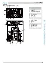
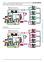
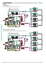
Figure 2-1.6: 30/32 layout of functional components
Legend
No. Parts name
1
Compressor
2
Discharge temperature switch
3
High pressure switch
4
High pressure sensor
5
Oil separator
6
Four-way valve
7
Heat exchanger
8
Electronic expansion valve (EXV)
9
Low pressure switch
10
Fan motor
11
Fan
12
Stop valve (liquid side)
13
Stop valve (gas side)
14
Plate heat exchanger
15
Accumulator
15
5
4
6
7
8
9
12
13
14
11
9
10
3
2
1


